36
INSTALLATION
June 1999
96-8000
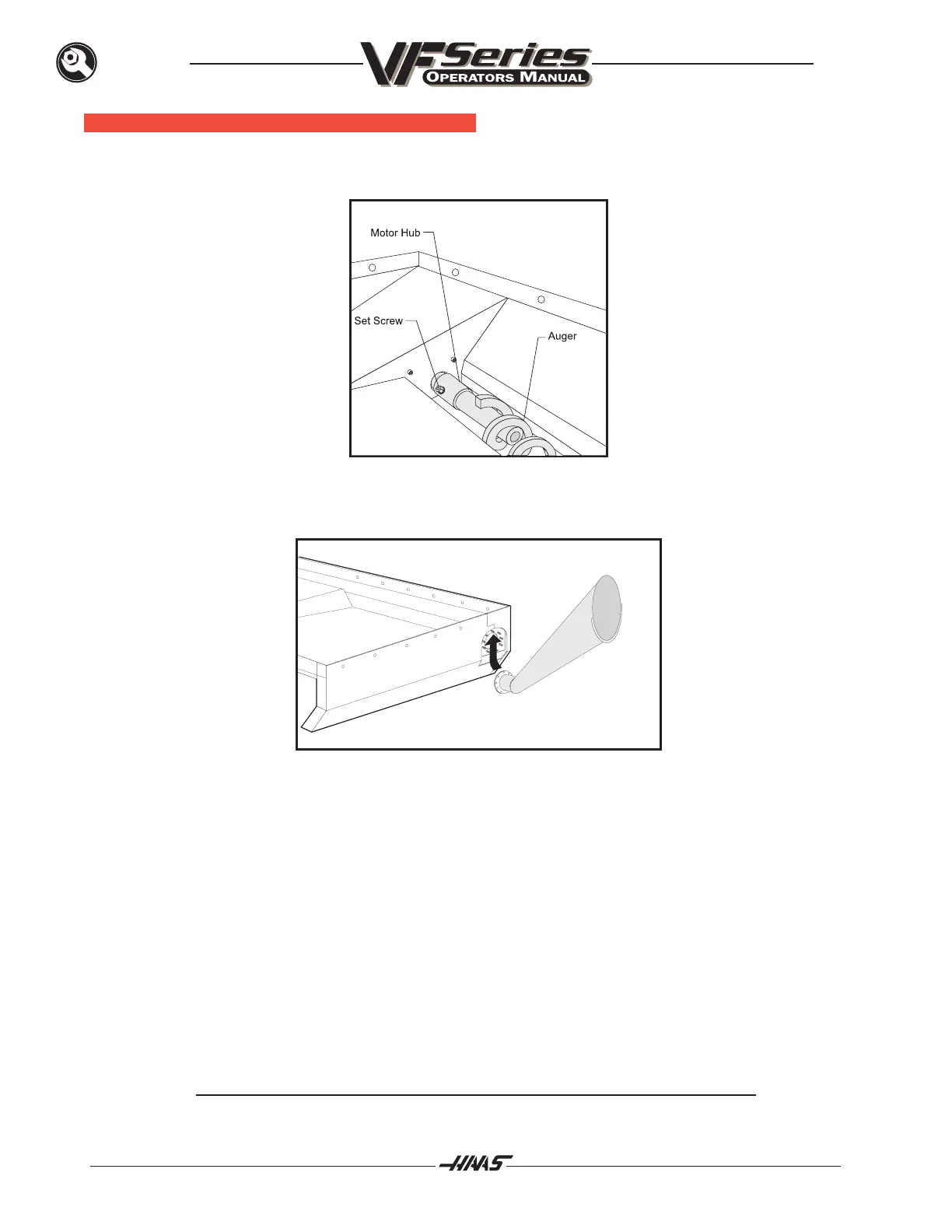
OPTIONAL C HIP A UGER I NSTALLATION
1. Unpack the auger and discharge tube.
2. Slide the auger into the discharge tube opening and then slip opposite end onto motor hub.
Fasten to motor hub with the 5/16-18 x 2½ bolt.
3. Install gasket and slide the discharge tube up and onto studs. Attach the eight nuts with locking
washers and tighten uniformly.
4. After machine start-up, check the operation of the auger to ensure the direction of rotation will
move the chips toward the discharge tube. If the auger is turning so that the chips are not being
moved toward the discharge tube, change the bit switch in PARAM 209 from 1 to 0 or 0 to 1 to
establish a new forward direction.
MAINTENANCE
During normal operation, most chips are discharged from the machine at the discharge tube. However, very
small chips may flow through the drain and collect in the coolant tank strainer and pan coolant drain (under the
pan). To prevent drain blockage, clean this trap regularly. Should the drain become clogged and cause coolant
to collect in the machines pan, stop the machine, loosen the chips blocking the drain, and allow the coolant to
drain. Empty the coolant tank strainer, then resume operation.
Note: Auger and discharge tube are subject to wear. Abrasive swarf, hard steel chips
and continuous use will accelerate this wear