54
INSTALLATION
June 1999
96-8000
MATERIALS REQUIRED
One crate (including pallet and 40 corner clips) 3/8" x 3" lag bolts (18)
3/8" washers (18) 6-mil plastic sheet
6-mil plastic cover Coolant box (cardboard)
Wire ties Foam pads
Fiber banding ½-13 x 10" bolts (4)
½" washers (4) ½-13 Nylock nuts (4)
16d nails (as required)
LOCK U P T HE M ACHINE F OR S HIPPING
1. Remove any tools from the tool carousel and spindle.
2. Clean the interior of the enclosure, including the windows, as necessary. After cleaning, spray all
metal parts around the way covers, table, spindle (including up into the spindle), with rust preven-
tive oil. (See the cautionary notes on cleaning the machine in the "Maintenance" section.)
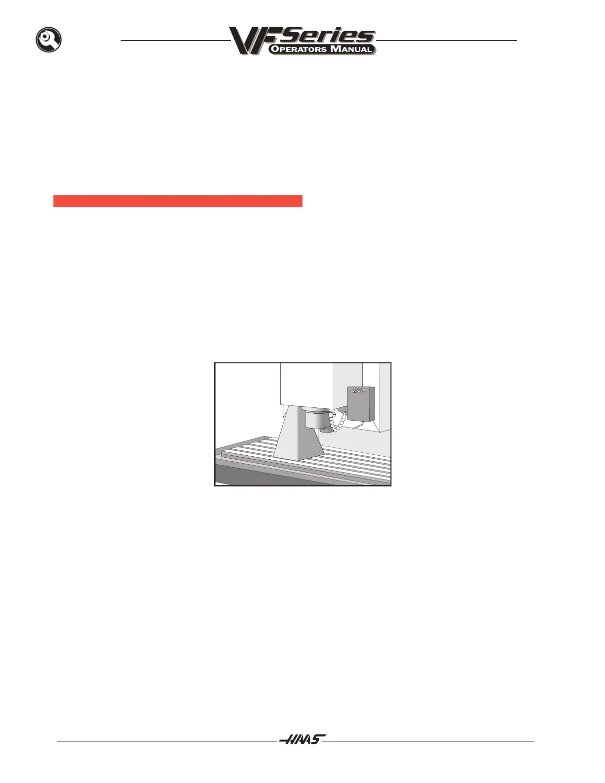
3. Use the jog handle to center the table under the spindle.
NEVER PUT ANY SUPPORT ON THE SPINDLE!! THIS WILL DESTROY THE SPINDLE BEAR-
ING!!!
4. Set the shipping bracket on the table, then use the JOG HANDLE to bring the head down until it
rests on the bracket. Attach the shipping bracket to the table and head with the four SHCS.
5. Press EMERGENCY STOP and the machine is locked up for shipping.
6. Power down (press the POWER OFF button at upper left of control).
7. Remove the discharge tube. Remove the chip conveyor from the motor hub. Pack them both for
shipping.
8. Place all loose items in the drain bucket. These items include the control cabinet key, washdown
kit, brush, leveling feet, and the leveling screws.
 Loading...

