CONTROLLER DETAILS
26
While in FIELD TEST mode, pressing FAULT HISORY displays the temperature read on the Outdoor Air Temperature Sensor, pressing
RESET / TEST displays the temperature read on the COIL Temperature Sensor, pressing MANUAL / TIME-TEMP DEFROST displays the
temperature read on the LINE Temperature sensor.
MANUAL / TIME-TEMP DEFROST BUTTON (GREEN)
Pressing this button for 1 second puts the Controller into MANUAL DEFROST mode immediately one time. When this button is
pressed for 5 seconds, the Controller toggles between DEMAND DEFROST initiation and TIMED DEFROST initiation.
SYSTEM STATUS AND FAULT CODES
IMPORTANTCall for Serviceat the outdoor unit to the thermostat.
For general status and In the event of a failure in the Acadia outdoor unit, the Controller has a built in diagnostic LCD 2-digit display
for diagnostic purposes. (Fig. 3, Appendix A) shows the location of the diagnostic LCD on the Controller. During normal operation
this LCD displays the current operation mode. If for any reason the Controller has encountered an error condition, the error may be
diagnosed using the fault descriptions in (Table 7).
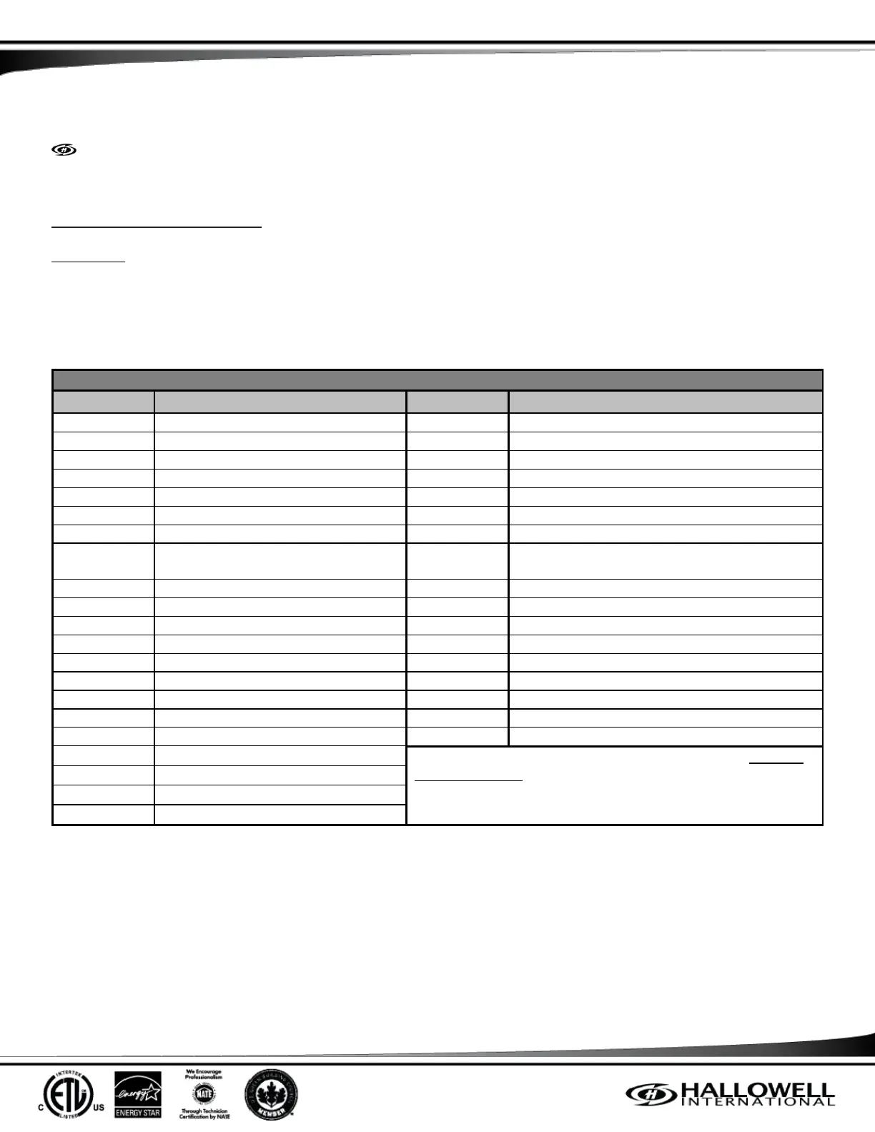
System Status and Fault Codes
High Pressure Switch Fault
Low Pressure Switch Fault
Line Temperature Sensor Fault
Field Test Mode (see 1 below)
Coil Temperature Sensor Fault
Ambient Temperature Sensor Fault
1 Cylinder to 2 Cylinder Primary
Compressor Protection Period
24VAC Short Circuit Fault
24VAC Under Voltage Fault
Abnormal Line Frequency Fault
Heat Mode 7 (see 2 below)
(1.) The “n” is the test number in that particular mode. Example:
F1, F2, H1, H2, etc.
(2.) A mandatory 10 minute shut down period; W1Out is
energized. This is known as a “Coffee Break”.
Defrost Mode 1: Initiation
Defrost Mode 2: Actual Defrost
Defrost Mode 3: Termination
Table 7: System Status and Fault Codes
In addition to the 2-digit display, there are four LEDs; Yellow, Blue, Green, and Red. These LEDs complement the 2-digit display and
indicate the status of the Controller. In case there is a fault condition and the home owner put the Controller in the Emergency Heat
mode, the Red LED shall be on, as well as the Yellow LED Flashing. Similarly, if the system is in Heat Mode and goes to Defrost
Mode, both the Yellow and Green LEDs are lit. If the Time-Temperature defrost initiation method is activated through the push
button on the Controller, the Green LED when the system is NOT in Defrost Mode.
The four LEDs and their flashing descriptions are described in (Table 7).