TROUBLE SHOOTING GUIDE
35
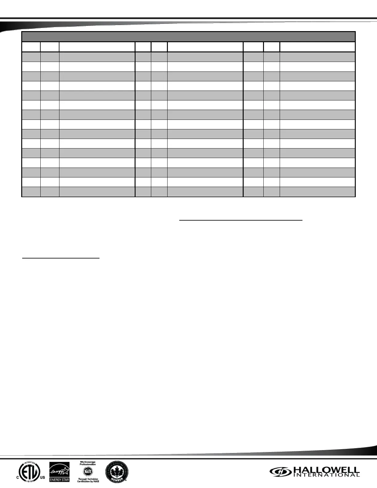
Temperature Sensor Resistances
Table 10: Temperature Sensor Resistances vs. Temperature
(NOTE) Table 10 has kΩ values. kΩ is measured as 1,000 Ω. Example: 100 kΩ = 100,000 Ω, 1.00 kΩ = 1,000 Ω.
If any of the sensors do not have a correct ohm reading ±2%, replacement is necessary. Contact the distributor that the system was
purchased from for replacement.
DEFROST TROUBLE SHOOTING
If the system is not defrosting or defrosting completely, these are the steps to take to determine the cause:
1. Check the air filter first. A plugged filter or even slightly blocked filter will not allow enough airflow over the indoor coil during
de Even restricted ductwork can cause the system to fail to defrost.
2. Make sure the snow is cleared from under the rails and under the coil, directly to the ground and the system has been installed
on appropriate snow legs. Even though ice is turned to water and allowed to flow towards the ground, the first frozen thing the
water hits will refreeze it and a cascade build-up effect occurs.
3. Make sure the snow is cleared from under the rails and under the coil, directly to the ground after EVERY snow storm. Build-ups
of snow and ice under the system need to be removed, sooner rather than later, and any snow drifts kept from forming up
against the sides.
4. Check the refrigerant charge as a last resort. To do this, remove the frost and ice with warm water; even cool tap water will
work. Putting the system into Manual Defrost is best; turning the thermostat OFF if the Manual Defrost does not clear the coil is
recommended. On average, a frozen coil can be defrosted in 20 minutes with tap water. Once the coil is bare, return the
system to the Heating M
accurate sub-cooling reading. After 30 minutes of run time, check the sub-cooling compared to the charging chart in (Table 14,
Appendix C).
(NOTE) Refrigerant charge should ONLY be added or removed if a severe discrepancy is found. Severity of this can only be
determined by the field technician and/or Hallowell International Technical Support.