EasyManua.ls Logo

Hallowell Acadia 024 - Table 11: Cooling and Heat Pump Airflow Taps for the Factory Supplied Air Handler

Default Icon
63 pages
Print Icon
To Next Page IconTo Next Page
To Previous Page IconTo Previous Page
Loading...
APPENDIX A - SETTINGS
38
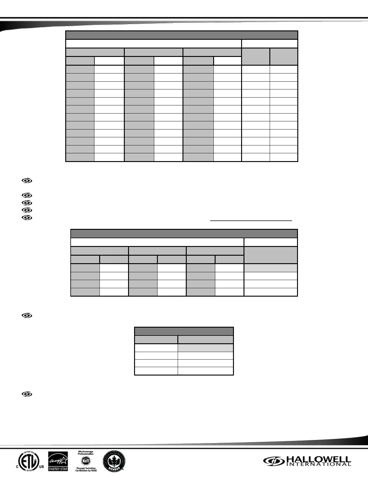
HIGH SPEED COOLING AND HEAT PUMP AIRFLOW (CFM)
Model
TAP SELECTIONS
24B
36C
48D
COOL
ADJUST
CFM
m3/min
CFM
m3/min
CFM
m3/min
1010
28.6
1230
34.8
2020
57.2
A
B
816
23.1
1007
28.5
1759
49.8
B
B
933
26.4
1202
34.0
1989
56.3
A
A
706
20.0
903
25.6
1607
45.5
B
A
926
26.2
1076
30.5
1790
50.7
A
C
594
16.8
965
27.3
1502
42.5
C
B
706
20.0
814
23.0
1439
40.7
B
C
505
14.3
714
20.2
1306
37.0
D
B
524
14.8
868
24.6
1368
38.7
C
A
448
12.7
646
18.3
1218
34.5
D
A
519
14.7
799
22.6
1246
35.3
C
C
447
12.7
604
17.1
1090
30.9
D
C
Table 11: Cooling and Heat Pump Airflow Taps for the Factory Supplied Air Handler
Both the COOL and ADJUST taps must be set for Cooling and Heat Pump Airflow (CFM). These are the minimums required by
the Acadia Outdoor Unit.
Fan only airflow (CFM) = 63% of high speed cooling.
Low speed cooling is used only with two-stage outdoor units. (Low speed is preset to 65% of the high speed cooling airflow.)
When operating in heat pump and electric heat modes, the airflow will be whichever is greater.
The airflow (CFM) indicator light, LED2, flashes once for every 100 CFM. Example: 12 flashes = 1,200 CFM.
ELECTRIC HEAT AIRFLOW (CFM)
MODEL
TAP SELECTIONS
24B
36C
48D
HEAT
CFM
m3/min
CFM
m3/min
CFM
m3/min
681
19.3
724
20.5
1318
37.3
A
607
17.2
657
18.6
1142
32.3
B
523
14.8
593
16.8
927
26.2
C
389
11.0
520
14.7
673
19.1
D
Table 12: Electric Heat Airflow Taps for the Factory Supplied Air Handler
The HEAT selection only controls airflow when Electric Heat is used, not for airflow during the Heat Mode.
DELAY COMFORT SETTINGS
DELAY
COMFORT SETTING
A
Normal
B
Humid
C
Dry
D
Temperate
Table 13: Delay Comfort Settings
The DELAY selection is for ramping up and down speeds for additional or not as much humidity removal during cooling.

Table of Contents

Related product manuals