26
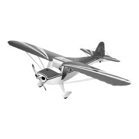
Step 5. Using a 1/16′′ drill bit, drill four pilot holes for the horn.
After the pilot holes are drilled, you can use the 3/32′′ drill bit to
complete the process.
Step 6. Trial fit the standard horn, using the four screws.
Carefully screw in the screws and engage the plastic plate on the
other side. We recommend covering the area around the horn
with masking tape to help prevent damage to the covering in
case the screwdriver slips. Once installed, repeat the process for
the left elevator.
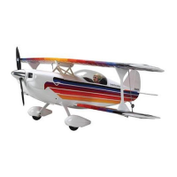
Step 7. Locate a standard and reverse control horn, four screws
and one plastic plate. The reverse “R” control is installed on the
right side of the rudder as if you were sitting in the cockpit. The
standard control horn will be mounted on the left. The rudder
pull-pull control horns will be located 7/16′′ back from the hinge
line of the rudder and approximately 3/8′′ up from the bottom of
the rudder. Mark the location with a felt tipped pen. Trial fit one
horn and make sure the location does not interfere with the tail
wheel wire that was inserted into the rudder.
photo 9-7
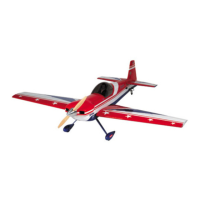
Step 8. Once you are satisfied with the location, mark the screw
holes with a felt tipped pen.
Photo 9-8
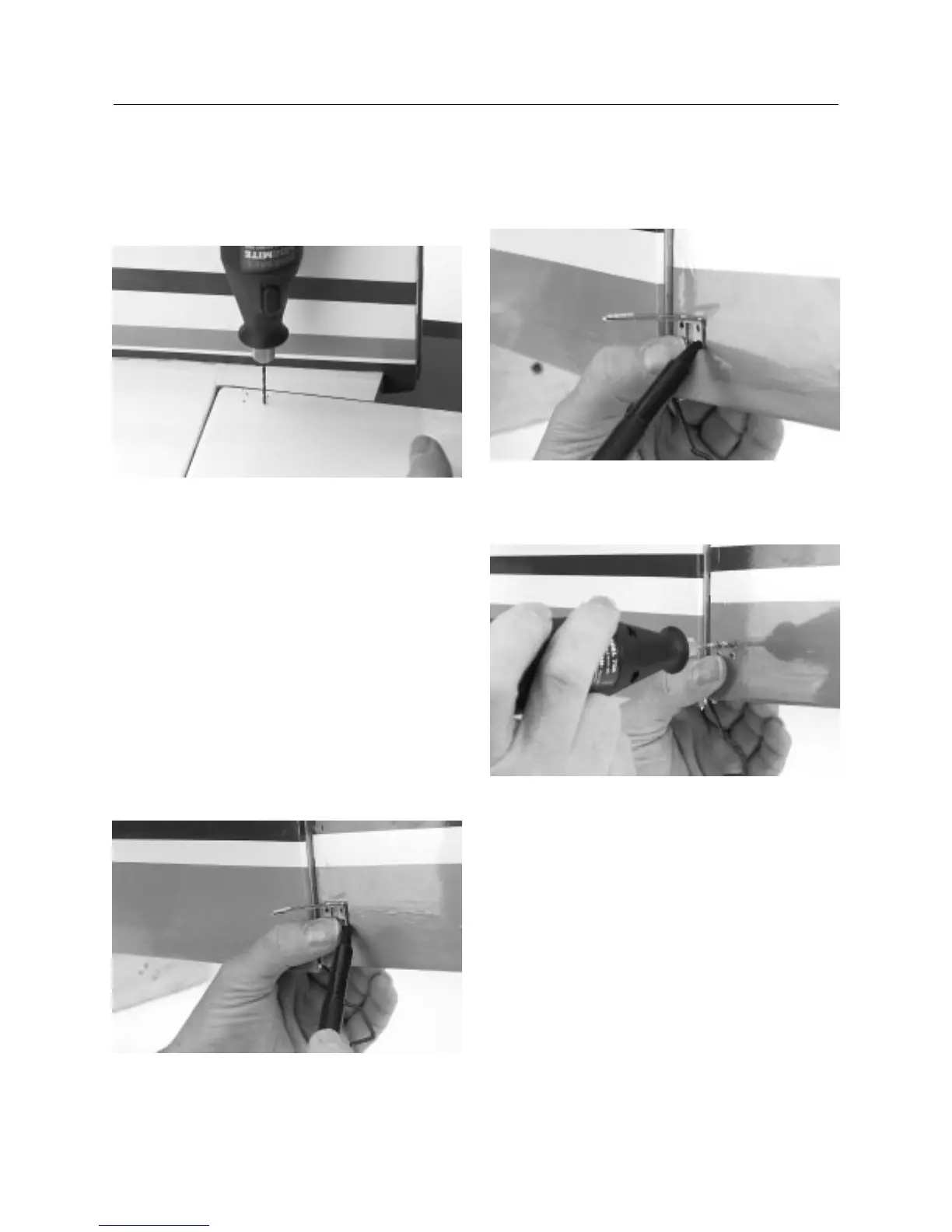
Step 9. Drill holes using the same procedure as described in
Step 5. Again, use caution when drilling so the wood is not split.
photo 9-9
CONTINUED
Section 9: Installing the Control Horns