14
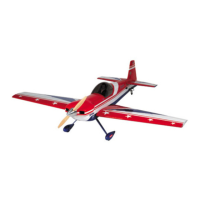
Step 1. For this assembly, you will be using a short (4”)
threaded rod, two clevis and a regular and reverse control horn.
Use the 4/40 nuts as locking devices to keep the clevis from
turning. There is also a locking clip that keeps the clevis from
opening. The reverse control horn has an “R” marked on its
base; the standard horn has no marking. For illustration
purposes, we will describe the hookup of the linkage on the right
wing panel.
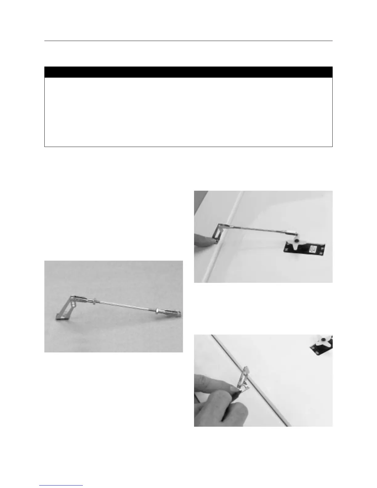
Step 2. Thread a 4/40 nut and clevis on each end of the
threaded rod. Next locate the standard horn. The mounting hole
plate should point toward the wing center. The link assembly
goes on the outer servo arm or the one pointing to the wing tip.
Step 3. To establish the length needed, trial fit the horn and
linkage to the servo arm. Adjustments in length are made by
screwing one or both clevis in or out. The control horn should be
positioned so the holes are over the center line of the hinge line.
Step 4. Once satisfied with the horn location (it should be a
straight line from the servo arm to the horn), mark the location
with a felt tipped pen. You will note the servo is positioned at an
angle to the wing, but is 90 degrees to the aileron hinge line.
Section 4: Installing the Aileron Linkage
• Wing assembly from Section 2
• Left control horn
• Right (reversed) control horn
• Plastic plate (2)
• Screws (8)
• Short (4′′) threaded rod (both ends) (2)
• Clevis (4)
• 4/40 nuts (4)
• Medium Phillips screwdriver
• Drill
• Drill bits: 1/16′′, 3/32′′
• Felt tipped pen
• Moto-Tool
Parts Needed Tools and Adhesives Needed