36
Step 1. The elevator linkage will be the first described, however
the construction sequence is up to the builder. Each linkage
(i.e., elevator, rudder and throttle) is approached differently. The
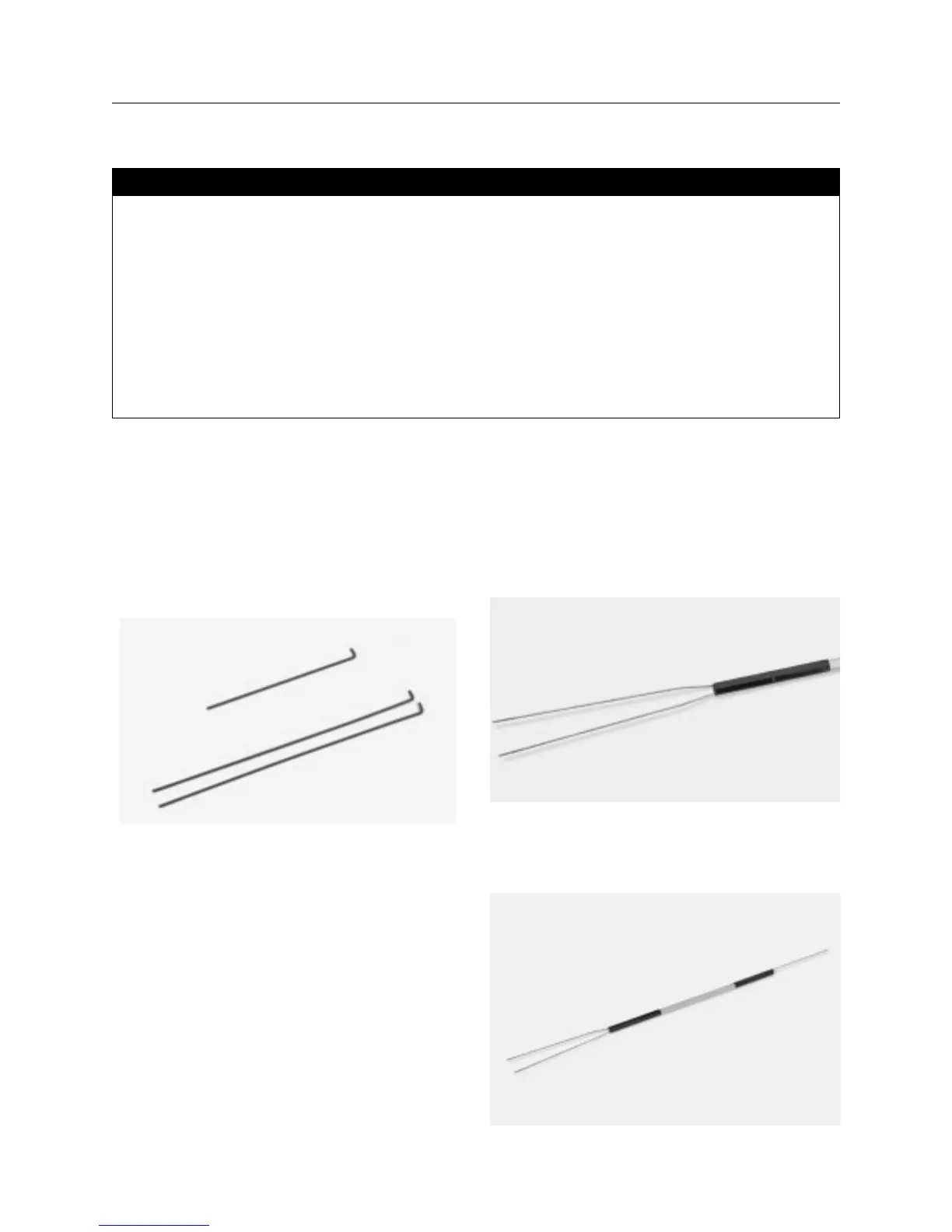
components for the elevator control linkage are made up of a
wooden rod, three threaded music wires, clevis and locking nuts.
Since the CAP 232 uses a split elevator, you will construct a
pushrod that has two threaded wires on one end for the two
elevators, and one shorter threaded rod to connect to the
servo horn.
Step 2. Drill a 1/8′′ hole 2′′ from each end of the wood rod. Bend
a 90 degree bend at the opposite end of each threaded rod. The
bent section should only be 1/8′′ to 3/16′′ long. Cut off any excess
material so the rods fit. Round out the holes so the rods fit flush
against the wood pushrod. A groove should be cut to help secure
the rods in place when applying the epoxy. Use string or nylon
thread to wrap the wire.
Step 3. Trial fit the two long threaded rods into the hole on either
side of the wood control rod. Cut a groove for both to help secure
the rods. Once you’re satisfied with the fit, mix 1/4 ounce of 12-
minute epoxy and apply it to the hole and area the rods will fit into.
Install the rods into the hole and wrap securely with nylon thread
or string. Coat the joint with epoxy and allow it to cure. Slide a
piece of heat shrink tubing over the end of the wooden pushrod
and, using a heat gun, shrink into place.
Step 4. Once the epoxy has cured, install the short rod on the
other end using the same proceed as described. Allow the epoxy
to cure completely before attempting to attach the clevis.
• Fuselage
•12′′ x 4-40 rod – threaded one end (2)
•6′′ x 4-40 rod – threaded one end
• 20” x 2mm rod – threaded one end w/nylon clevis
• .020 music wire 36′′
• 2-56 clevis w/clips (4)
• 2-56 threaded couplers (4)
• 2-56 lock (hex) nuts
• Wood pushrod
• 4-40 clevis w/clips (3)
• Shrink tubing
• Soldering iron
• Silver solder (Stay Brite)
• Needle nose pliers
• 12-minute epoxy
• String or nylon thread
• Rubbing alcohol
• Paper towels
• Drill
• 1/8′′ drill bit
Parts Needed Tools and Adhesives Needed
Section 15: Installing the Control Linkages