37
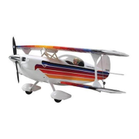
Step 5. The pull-pull type of linkage will be made up of music
wire, two threaded couplers, two clevis and locking nuts. You
will need to make two sets of linkages.
Step 6. Scrape or clean the ends of the wire. Using a soldering
iron, silver solder one of the threaded couplers to one end of the
music wire.
Note: It’s important to bend over approximately 3/8′′ of the
music wire onto itself at the ends using a pair of pliers. This will
give a more secure mechanical solder joint as the silver solder
has more to “grab onto” than a straight end.
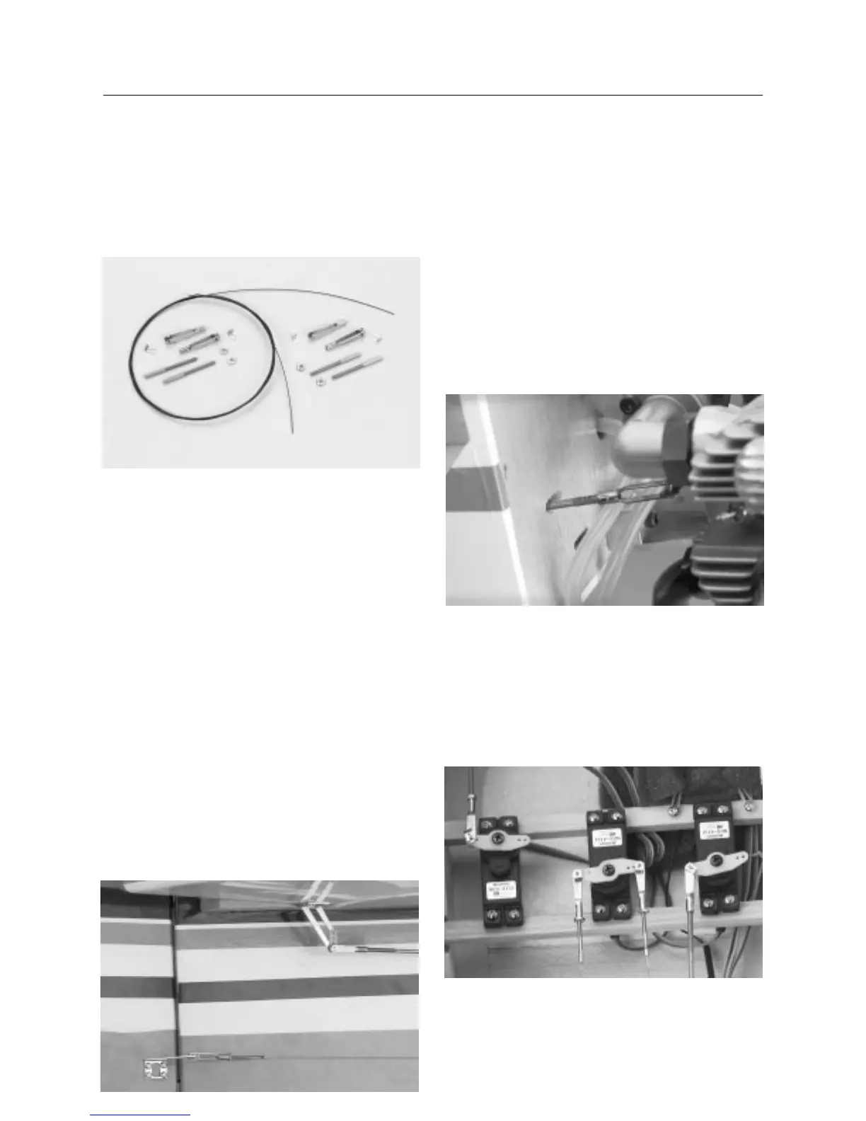
After the solder has cooled, check the security of the solder
connection by pulling on the connection. Attach a locking nut
and a clevis on the threaded coupler, and thread the other end
through the fuselage. Trial fit the linkage to the servo arm of the
rudder servo, compensating for the fact there will be a threaded
coupler and clevis attached. Once you’re satisfied with the
length, silver solder the coupler to the music wire. After the
solder has cooled, again check the security of the joint. Make up
a second linkage using the previous procedures. Once both
linkages have been constructed, trial fit in place by connecting to
the control horns of the rudder and servo. Final length
adjustments can be made at either or both ends of the linkage by
screwing the clevises in or out as needed.
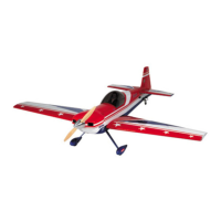
Step 7. Locate the threaded rod for the throttle (2mm). Trial fit
the rod and note where it will pass through the fuselage formers.
There is a slotted opening on the firewall in the approximate
location of the carburetor arm, however you may have to make
adjustments as to where the holes need to be located. Once you
are satisfied as to the linkage path, drill the holes in the fuselage
former and, if necessary, in the firewall. A 1/8′′ hole should
provide ample room for the linkage. Begin installing the throttle
control rod by attaching the clevis to the threaded end of the rod.
Thread the throttle control rod through the firewall and attach the
clevis to the engine throttle control arm.
Step 8. Note where the throttle control rod is in relation to the
throttle servo arm inside the fuselage. You will need to make a
Z-bend at the end of the rod and attach it to the throttle servo
arm. Make sure the engine carburetor barrel is in the
1
/
2
open
position. This will allow for minor adjustments to the carburetor
opening by screwing the clevis in or out. Adjust so the throttle is
at half throttle when the servo is electronically centered.
CONTINUED
Section 15: Installing the Control Linkages