33
Step 5. Slide the two plastic caps over the brass tubes as
shown. Note the orientation of the caps. The small inside cap
and the “peg” faces away from the black rubber stopper. The
large outside cap and the “raised center” faces away from the
black rubber stopper.
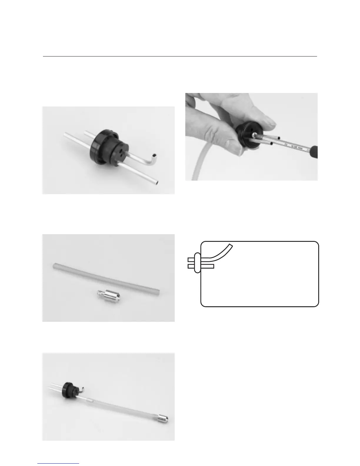
Step 6. Locate the small diameter fuel tubing. This tubing will
be used for the fuel pickup inside the fuel tank. Insert the clunk
into one end of the fuel tubing.
Step 7. Install the open tube end of the tubing onto the pickup
brass tubing.
Step 8. Insert the 3mm screw into the center hole of the stopper
and tighten it until it just threads onto the black cap on the other
side of the rubber stopper.
Step 9. Carefully insert the assembly into the fuel tank. Note the
position of the vent tube. It must be at the top of the fuel tank to
function properly. Be sure the vent is positioned at the top. The
length of tubing can be shortened by cutting it with a sharp
hobby knife.
Step 10. Tighten the 3mm screw. This will allow the rubber
stopper to form a seal.
Important: Remember which tube is the fuel pickup and
which is the vent so you can properly connect
the fuel tank to the engine.
Step 11. Install fuel tubing onto the tubes and feed it through
the holes in the firewall as you press the fuel tank into position.
Foam in the tank compartment can be used to provide some
vibration damping and help support the fuel tank (foam not
included). Some trimming of the fuel tank location may be
necessary to fit the tank into the fuselage. Bend the brass tube
outside the tank to line up with the holes in the firewall.
CONTINUED
Section 13: Assembling and Installing
the Fuel Tank