73
1.1.1 Working principle
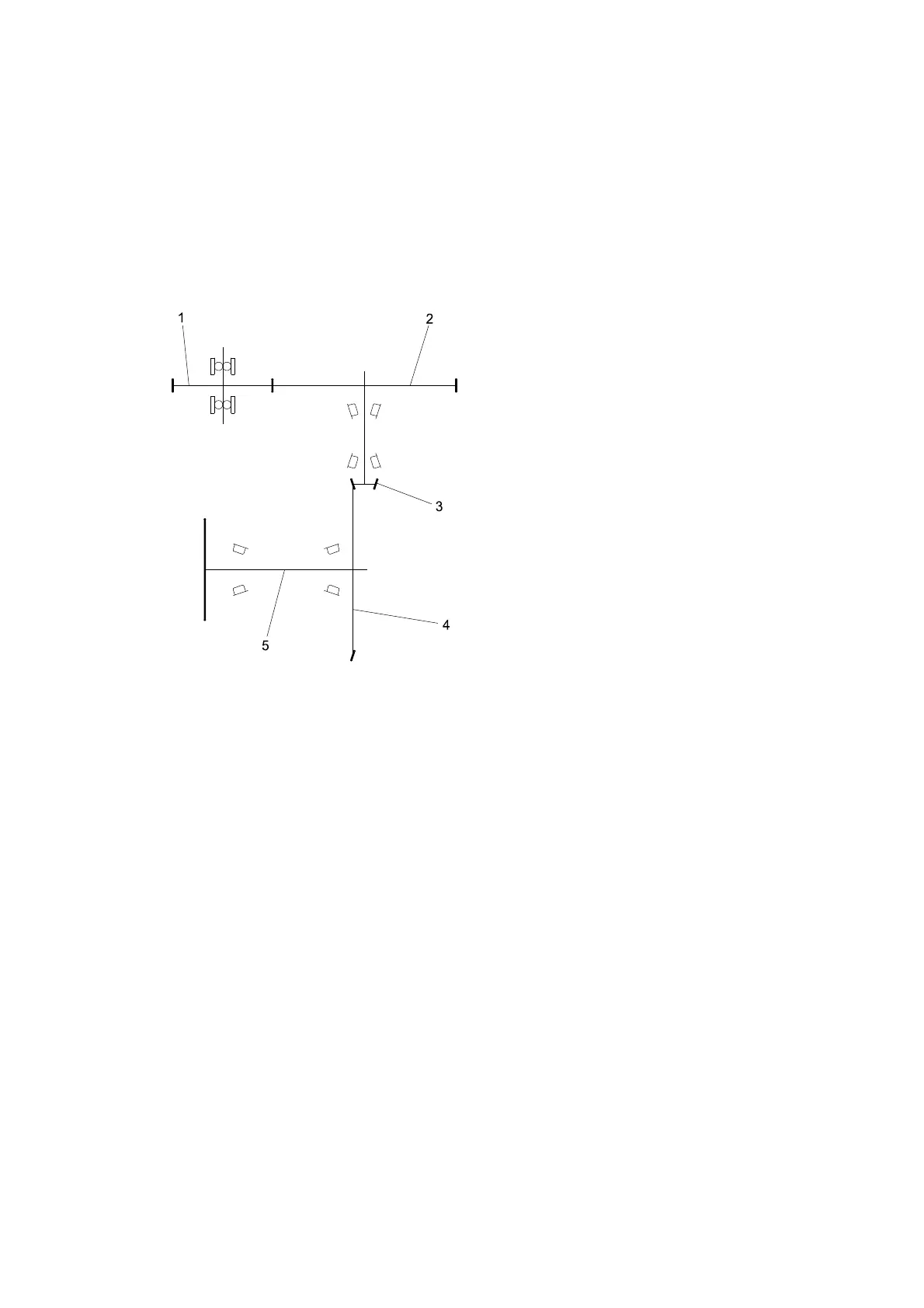
Simple figure of reduction box is as Fig.2-3, motor driving gear 1 drives driven gear 2, driven gear
2 drives driving spiral bevel gear 3 to transfer to driven spiral bevel gear 4, then the driven spiral
bevel gear 4 drives the output of output flange 5. Power transmission order is that 1(driving motor),
2(driving gear), 3(driven gear), 4 (gear shaft), 5 (annual gear) drive the wheel output. Moreover,
this reduction box does not need to shift, but realize direction shift (forward or reverse) directly by
motor positive inversion, and is easy to use and maintain.
1. Driving gear(pinion gear)
2. Driven gear
3. Driving spiral bevel gear
4. Driven spiral bevel gear
5. Output flange
Fig.2-3 Drive picture of reduction box