9
Mounting Dimensions & Instructions
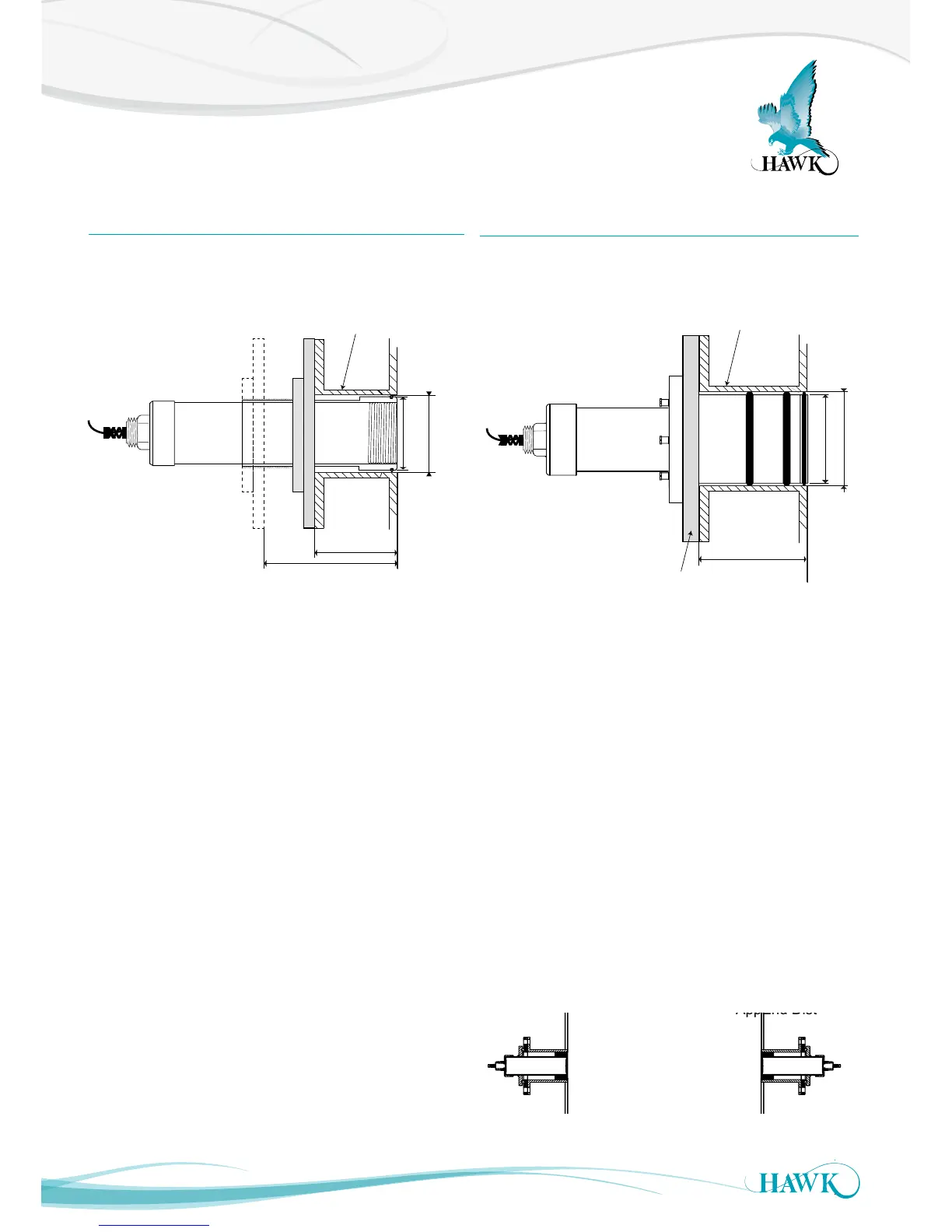
Gladiator Acoustic Switch Series
C
A B
STANDARD 4” ANSI FLANGE DIMENSIONS
FLANGE A (PCD) B (OD)
TYPE mm in. mm in.
C (Hole)
mm in.
FA4 190.5 7.5 228 9.0 19 0.75
SIZE
4”
No.
Holes
8
100mm (3.9”)
102mm (4.0”)
123mm (4.8”)
Flange
3 x O-rings
100mm (3.9”)
min.
95mm (3.7”)
max. 165mm (6.5”)
102mm (4.0”)
ID 100-102mm (3.9-4”)
Pipe with 4” ANSI interface
Adjustable Flange Range
ID 100-102mm (3.9-4”)
Pipe with 4” ANSI interface
General Mounting Instructions
• The mounting location must be away from the
material flow path.
• Sleeve face should be flush with vessel wall interior
• O-rings form both a steal and act as acoustic
de-coupling with the vessel. If required use a cavity
filler (such as a silicone) to prevent material ingress
around the sleeve.
• Material ingress between the sleeve and mounting
can create acoustic coupling which can reduce
sensor performance
• If there is potential for sensor face wear, the
titanium version must be used
• If there is potential for high volume rock impact,
consider a protective hood above (not in front of)
sensor face location.
• Avoid mounting close to perpendicular walls where
material build up can bridge to the Transducers.
• Avoid mounting close to perpendicular walls where
material build up can bridge to the Transducers.
C
A B
STANDARD 4” ANSI FLANGE DIMENSIONS
FLANGE A (PCD) B (OD)
TYPE mm in. mm in.
C (Hole)
mm in.
FA4 190.5 7.5 228 9.0 19 0.75
SIZE
4”
No.
Holes
8
100mm (3.9”)
102mm (4.0”)
123mm (4.8”)
Flange
3 x O-rings
100mm (3.9”)
min.
95mm (3.7”)
max. 165mm (6.5”)
102mm (4.0”)
ID 100-102mm (3.9-4”)
Pipe with 4” ANSI interface
Adjustable Flange Range
ID 100-102mm (3.9-4”)
Pipe with 4” ANSI interface
Remote Transducer
With GAWSLV-3-X and FA4A-4 Flange
Remote Transducer with Spray Cleaner
With FA4A-4-ASC Flange
• Transducers should be aligned as accurately as
possible for optimum performance.
• Never use the connection cable to carry or extract
the Transducer
Spray Kit Mounting Instructions
• Solenoid and 4 way pipe converter should be
mounted securely.
• Recommend 4 way pipe converter is kept close to
mounting position on transducer - use 1” single pipe
for as much distance as possible.
• Use a converter if required to interface with 1”
HAWK recommended pipe connection.
ChuteWidth
AppStart Dist
AppEnd Dist
Live Measured Range
Distance Between
Transducers
Min. 400mm (15.7")
Minimum Range