10
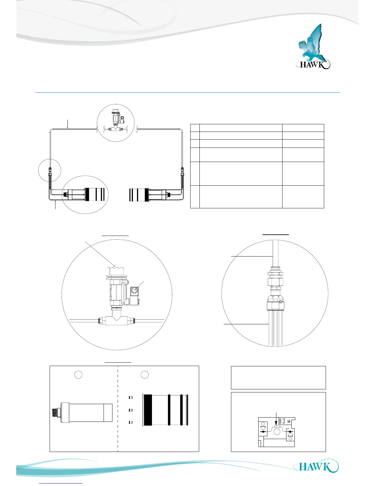
GAWC-SYS1 Acoustic Cleaner Components
A
C
B
D1
D2
1” BSP INT THD on Solenoid
Water connection size
determined by end user
Detail A
Solenoid
Plug Socket
C1
C2
Detail C
Ø12mm Tube
Ø6mm Tube
Detail B
D1
D2
Part Description Part Number
C1 Hawk Transducer
C2 Cleaner Sub-assembly GAWC-X
AWRT15_______AS
*
SolenoidA
0.5” to 4 x 1/4” connecterB
GAWC-SL
GAWC-4P
D1
Ø
12mm tube
Supplied in single piece
Total length = distance of part A to part B x 2
(one length per transducer)
D2
Ø
6mm tube
Supplied in single piece
Total length = distance of part B to part C x 8
(Four equal lengths per transducer)
GAWC-12MMLz
GAWC-06MMLz
z = Specify length in metres
*Consult Acoustic Switch datasheet
for full transducer part numbering
1
2
1N4004 Diode
Wiring Diagram for Solenoid Plug Socket
Max. water pressure 14bar (1400kpa)
Min. water pressure 1bar (100kpa)
Note: Full cleaner package GAWC-SYS1 includes all converters,
reducers, connecters, 30m of 12mm tube, 20m of 6mm tube, solenoid
and FA4A-4-ASC flanges. It does not include other eletronics
(transducers, amplifier, junction box).
System Overview
Gladiator Acoustic Switch Series