15
C6A
A0638−2.3 en/de/fr HBM
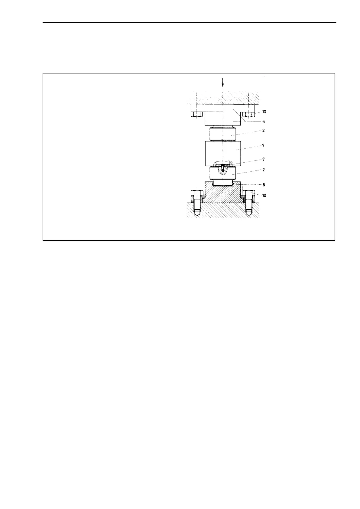
The execution as a pendle bearing shown in Abb. 5.4 allows lateral shifting of
a bearing point (max. diagonal position of the pendle bearing axis approx. 1 to
2°).
Only for nominal forces < 2 MN
F = direction of force; 1= transducer; 2= load button; 4= pressure plate; 5= substructure; 6= pendle bea-
ring top section EPO3; 7= centering disc; 10= fixing bolts
F
Abb. 5.4: Installation with pendle bearing EPO3
No transverse forces can thus occur in the bearing. The pendle bearings must
stand vertical in the normal case in order to allow lateral excursion. On
installation guide elements must be provided here.