17
C6A
A0638−2.3 en/de/fr HBM
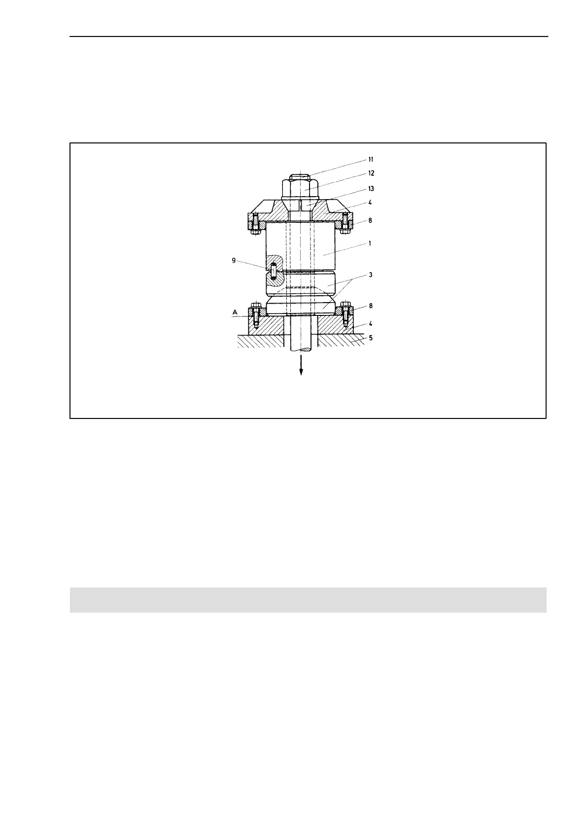
5.3.4 Tensile force introduction with spherical cap ZK
Thanks to its inner bore, the C6A transducer designed for compressive
loading (nominal force ≤2 MN) can also be used for measuring tensile loading
(Abb. 5.7).
Nominal forces < 2 MN
F = direction of force; 1= transducer; 3= spherical cap; 4= pressure plate; 5= substructure; 7= centering
disc; 8= centering ring; 9= centering pins (3 on circumference); 11= tension anchor (tension rope);
12= tensioning nut; 13= retaining ring
F
Abb. 5.7: Installation for tensile loading
To do this the tension element is fed through the inner bore of the transducer.
The tensile force then acts like a compressive loading. Here the tensile
strength of the tension element used is particularly to be noted since − due to
the diameter of the inner bore of the transducer − high tension stresses occur
at the nominal load.
Please note in particular section 5.4 (“Safety measures).
5.4 Safety measures
An overload cut−out should be provided wherever possible. Due to the small
displacements (see Specifications) the stops must be able to be set very
finely and secured well. The overload cut−out should not prevent
measurement at up to 120 % of the nominal force and be fully effective from
140 % of the nominal force.
Fall safety devices must additionally be provided, particularly where overload
could result in personal injury.