19
C6A
A0638−2.3 en/de/fr HBM
6.2 Wiring pin assignment
The connection cable of the transducer has colour−coded free wire ends. The
cable shielding is connected in accordance with the Greenline concept. This
means that the measurement system is surrounded by a Faraday cage.
Electromagnetic interference will not affect the measurement system.
Connectors to CE standard are to be fitted at the free end of the transducer.
The shielding is here to be laid over the whole area.
If a different connection technique is used then good EMC shielding is to be
provided in the wiring loom, the shielding again being laid over the full area
(see also HBM Greenline Information, document G36.35.0).
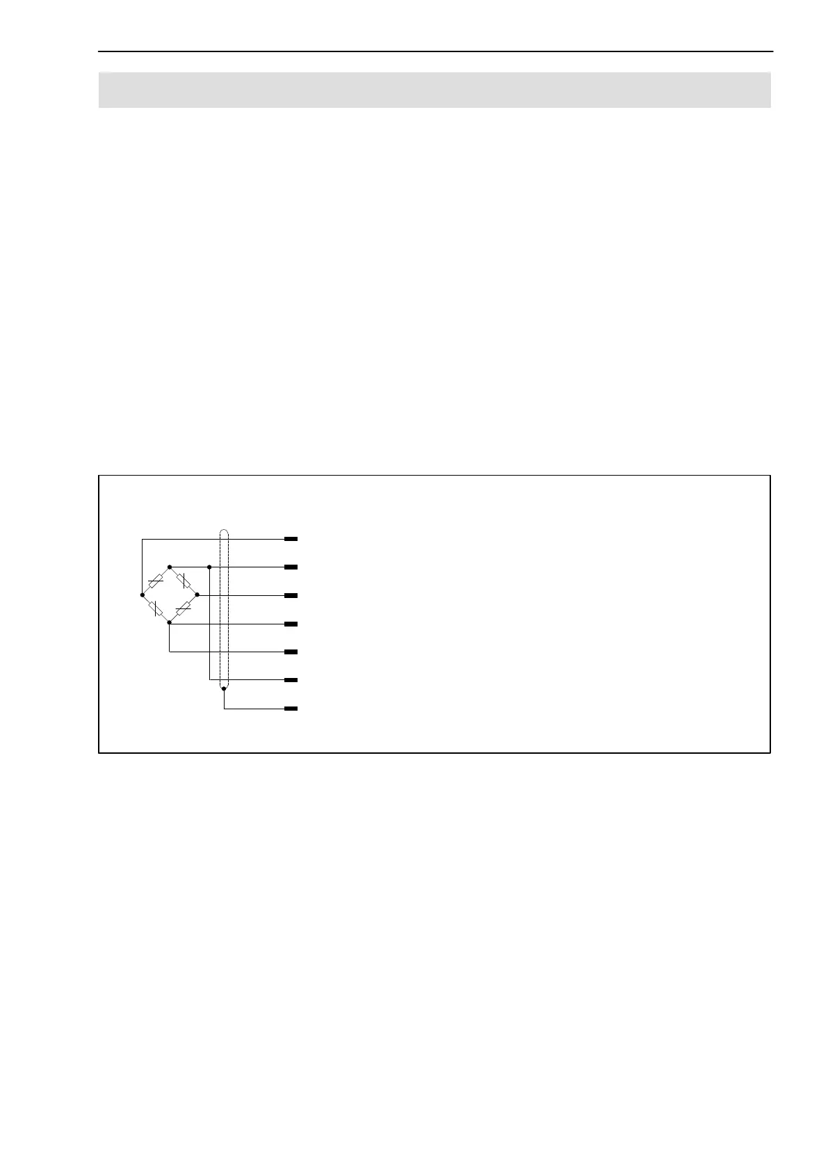
If the transducer is connected according to the following connection diagram
then when the transducer has compressive loading the output voltage at the
measuring amplifier is positive.
wh (white)
bk (black)
rd (red)
bl (blue)
gn (green)
gy (grey)
shielding
Measurement signal (+) U
A
Excitation voltage (+) U
B
Sense lead (−)
Sense lead (+)
Excitation voltage (−) U
B
Measurement signal (−) U
A
Cable shielding, connected to housing
Six−wire connection
Fig. 6.1: Pin assignment for the C6A