C6A
14
A0638−2.3 en/de/frHBM
When planning the structure ensure that the pressure plates (4) (see Abb. 5.1
to Abb. 5.4) are hardened (HR
C
42 − 46) and ground so as to be plan−parallel
(evenness ±0.02 mm) (for minimum thickness see table below). The
substructure must be sufficiently unyielding. To centre the transducer with
nominal loads ≤2 MN it is recommended that centering discs (7) are used
(see Abb. 5.1 to Abb. 5.4). The exact dimensions of these discs which are to
be produced should match those of the centering discs of the loading heads
(section 8.2). If the transducer is fixed with the fixing bolts (10) (see Abb. 5.1,
Abb. 5.2 and Abb. 5.4) ensure that when the fixing bolts are screwed in the
maximum tightening torque M
A
specified in the table below is not exceeded.
Nominal force
MN
0.2 0.5 1 2 5 10
Maximum tightening torque M
A
*)
N⋅m
8 20 25 40 90 400
Thickness of the pressure plates where
HR
C
42 − 46
mm
>30 >40 >50 >70 >90 >120
*) for bolts of resistance class 8.8
If the bolts are tightened too firmly this will result in changes in the zero signal
and the characteristic values. If possible, the fixing bolts should not absorb
any lateral forces! They are to be screwed in with a liquid thread securing
medium.
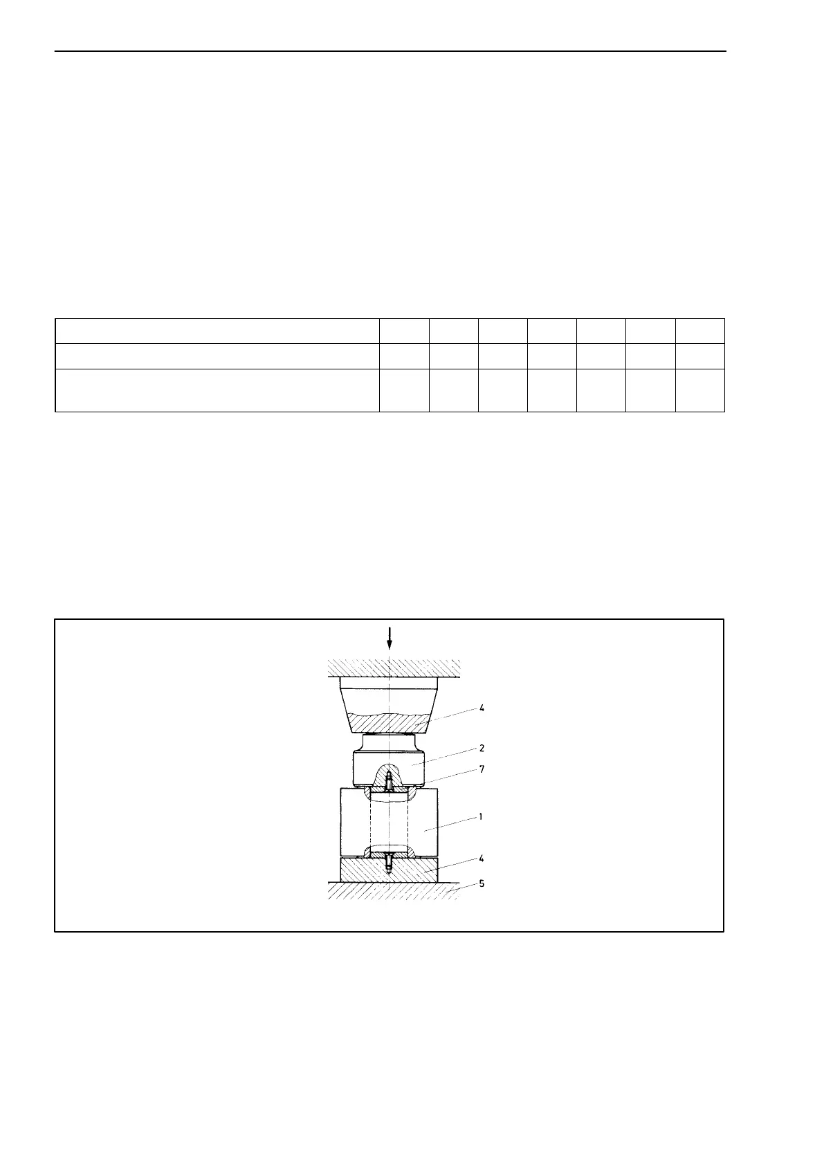
5.3.2 Force conductor with load button ZL and pendle bearing EPO3
Only for nominal forces < 2
MN
F = direction of force; 1= transducer; 2= load button; 4= pressure plate; 5= substructure; 7= centering disc
F
Abb. 5.3: Rigid installation of the C6A with ZL and EPO3
No transverse forces may occur with this installation arrangement. Instead of
the pressure plate (4) the pendle bearing top section EPO 3 may be used with
load button ZL. For the execution of the substructure refer to section 5.3.1