44
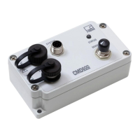
CMD600
A2820−1.1 en
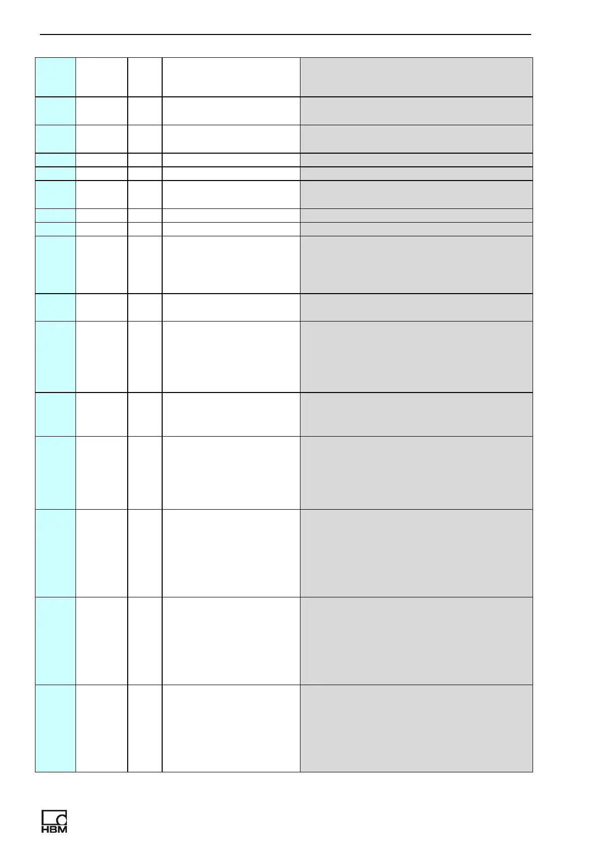
Num
ber
Protecti
on
Glo-
bal
Default value Description
13 N N 0.0000E+00 LPF frequency [Hz]
(min=1,max=20000).
14 N N 0.0000E+00 HPF frequency [Hz]. Possible
frequencies: 0, 0.2, 2.
15 Y Y 6.1841E−10 Integrator capacitor (smaller)[C/V].
16 Y Y 6.6708E−8 Integrator capacitor (bigger) [C/V].
17 N N 2.0000E+10 Channel gain [V/C]. Limited with
parameters 17 and 18.
18 Y Y 1.6667E+7 Min channel gain [V/C]
19 Y Y 2.0000E+11 Max channel gain [V/C]
20 N N 0 Select analog mode.
Mode 0: measured value
Mode 1: Peak to peak value
Mode 2: −Peak Mode 3: +Peak
21 N Y 0 Polarity and enable/disable of digital
input.
0..disable input, active logical state is 1
1..disable input, active logical state is 0
2..enable input, active logical state is 1
3..enable input, active logical state is 0
22 N Y 0 Mode for digital input (0..cleak peak
values, 1..output signal hold,2..param.
switch)
23 N N 0 Digital mode for output 1.
0..state of limit switch
1..overload
2..SW controlled output
3..system error
24 N N 0 Polarity and enable/disable of digital
output 1.
0..disable output, active logical state is 1
1..disable output, active logical state is 0
2..enable output, active logical state is 1
3.. enable output, active logical state is 0
25 N N 0 Digital mode for output 2.
0..state of limit switch
1..overload
2..SW controlled output
3..system error
4...param. switching
26 N N 0 Polarity and enable/disable of digital
output 2.
0..disable output, active logical state is 1
1..disable output, active logical state is 0
2..enable output, active logical state is 1
3.. enable output, active logical state is 0