DAC-42(A)-x-PN
Page 51
DAC-42(A)-x-PN
Manual
Revision: 1.0
22.01.2024
9.5.2 Version for Mode 1 (open loop, one valve with two solenoids)
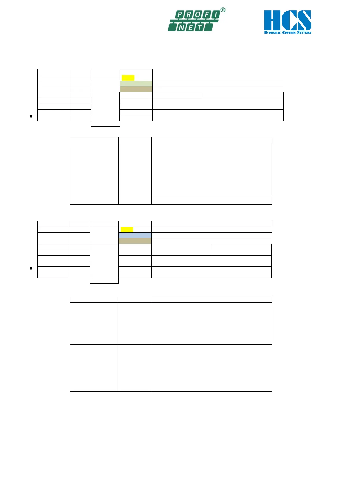
Master writes multiple parameters (at all 8 bytes)
Write first…
Comment Byte Structure Abbreviation
Description
Telegram
header
Telegram address, defined by User, Range 0..255, 0..0xFF
Command: 15 = Write multiple parameter by the master
Module
Data
Byte for special functions
A1.01 Module 1
Set value input (
Profinet
)
5 DAT1.2L
A1.02 Module 1 (normally not used)
Set value input (Profinet)
….Write last
8
Overall telegram length in bytes
Explanation of Byte for special functions (Control byte)
Description Abbreviation
Function of each bit
Byte for special
functions
DATx.1
Can be set only if the hardware enable is active.
0x01 = not used
0x04 = TST_CMP; Set Error/Comp output direct to 24V
(disable signalizing of error output)
0x10 = not used
0x80 = BUS_DISABLE (Module disable via Profinet)
In this mode not applicable, reserved:
0x02 = CNTRL_1
0x08 = CNTRL_2
0x20 = CNTRL_3
The special function byte will be set to internal 0x00 (reset)
when the hardware enable is inactive.
Response telegram:
Write first…
Comment
Byte
Structure
Abbreviation
Description
Telegram
header
Telegram address, defined by the write command
Command: 15 = Write multiple parameter by the master
Data of
SADR
Module
Status word
VALUE1 = d1.07
Actual current A
VALUE2= d1.08
Actual current B
….Write last
9
Overall telegram length in bytes
Explanation of High and low byte of module state (Status word):
Description Abbreviation
Explanation of each bit
High byte of module
state
DAT.1H
0x01 = Digital input SP1 (S1.01) active *)
0x02 = Digital input SP2 (S1.02) active *)
0x04 = HW_ENABLE, hardware enable active
0x08 = ERROR, Error is pending
0x10 = Digital input SP3 (S1.03 active *)
0x20 = Digital input SP4 (S1.04 active *)
0x80 = BUS_DISABLE is set
In this mode not applicable, reserved:
Low byte of module
state
DAT.1L
if „Error occurred” bit is set: error number
otherwise:
0x01 = not used
0x02 = not used
0x04 = not used
0x08 = not used
0x10 = not used
0x20 = not used
0x40 = not used
*)
The designation and availability of the input depends on the module variant.