02/11/98
40
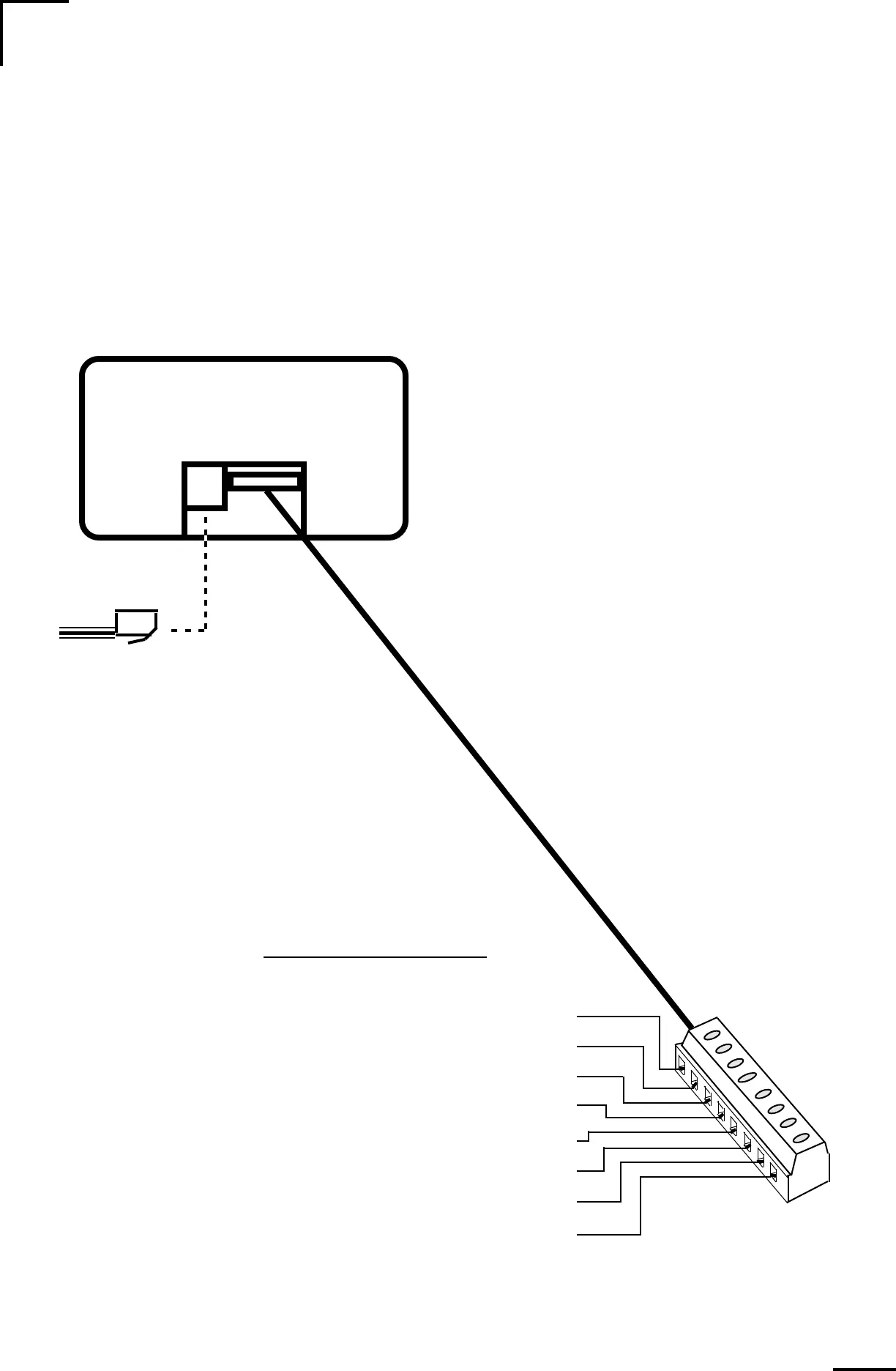
Make the necessary wire connections to the
Link
1000
as shown in the following diagram:
CAUTION
Use correct sized screwdriver for terminal
screws. Tighten firmly but do not over-tighten
to avoid damage.
NOTE: The screw terminal is a small part.
During assembly and testing, the screw ter-
minals are tightened. To accomodate wires,
loosen the screws and pry open the wire
clamp with a paper clip. The holes will ac-
cept 16 AWG wire IF you have a clean cut,
clean strip and twist the wires tightly. Use
needlenose pliers to insert the wires.
DC - Meter Negative (BLACK) [1]
Shunt Sense Lead Load Side (GREEN) [2]
Shunt Sense Lead Battery Side (ORANGE) [3]
Battery Volt Sense (0.1 - 50V DC)(BLUE) [4]
DC + Meter Power (8 - 40V DC) (RED) [5]
Battery #2 Voltage Sense Lead (VIOLET) [6]
Not Used [7]
Not Used [8]
Top Rear View
BACK OF
UNIT
WIRING CONNECTIONS TO THE
Link 1000