130 6 Programming: Programming Contours
6.2 Fundamentals of Path Functions
Entering more than three coordinates
The TNC can control up to 5 axes simultaneously. Machining with 5
axes, for example, moves 3 linear and 2 rotary axes simultaneously.
Such programs are too complex to program at the machine, however,
and are usually created with a CAD system.
Example:
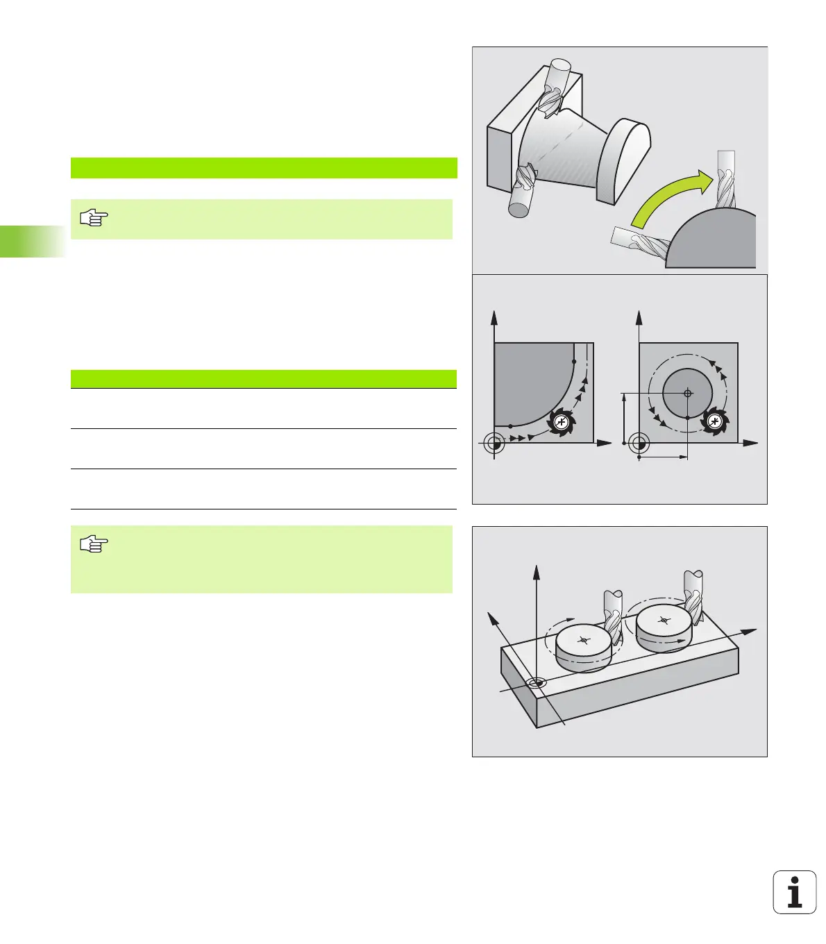
Circles and circular arcs
The TNC moves two axes simultaneously in a circular path relative to
the workpiece. You can define a circular movement by entering the
circle center CC.
When you program a circle, the TNC assigns it to one of the main
planes. This plane is defined automatically when you set the spindle
axis during a TOOL CALL:
Direction of rotation DR for circular movements
When a circular path has no tangential transition to another
contour element, enter the direction of rotation DR:
Clockwise direction of rotation: DR–
Counterclockwise direction of rotation: DR+
L X+20 Y+10 Z+2 A+15 C+6 R0 F100 M3
The TNC graphics cannot simulate movements in more
than three axes.
Tool axis Main plane
ZXY, also
UV, XV, UY
YZX, also
WU, ZU, WX
XYZ, also
VW, YW, VZ
You can program circles that do not lie parallel to a main
plane by using the function for tilting the working plane
(see “WORKING PLANE (Cycle 19),” page 330) or Q
parameters (see “Principle and Overview,” page 356).
X
Y
X
Y
CC
X
CC
Y
C
C
CC
CC
DR–
DR+
X
Z
Y
 Loading...


