USDE
Automation Instructions CPK • 10-2015 •106-29009
Technical data
23
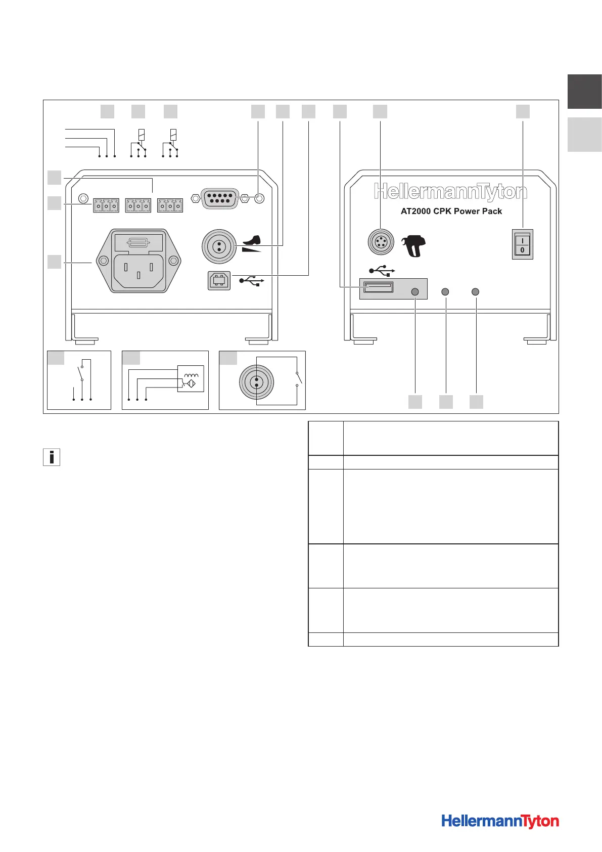
7.2.1 Overview of interfaces, power pack with
control box
Last TieError Busy
External
max. 250V~
Data SignalPower
A-1 A-2 2-1
11
12
1A B C 4 5
9 8 7
62 3
10
123 123123
123 123
BN
NPN
BK
BU
1 Socket for serial interface (D-SUB plug-in connector)
2 Socket for foot-operated switch (required only for bench mount kit CPK)
The socket for the foot-operated switch is deactivated when
the interface to the PC is activated.
3 USB (B) port for connection to PC
4 USB port for exporting process data to USB memory stick
5 Socket for connection to tool
6 Main switch
7 LED indicator Power
Green: Power pack with control box switched ON
8 LED indicator Signal
Green: AT2000 CPK Connected and ready,
Red: Fault,
Yellow: Binding cycle active,
Blue: Navigation in main menu, binding not possible
9 LED indicator Data
Green: PC connected; AT2000 CPK connected; USB stick found; USB
stick can be removed,
Red/green flashing: Data is being written to USB stick
10 Socket for power supply
11 Sockets for an external sensor
12 Error/Busy: Freely assignable relay outputs
A Last Tie: Sensor input signal, e.g. or monitoring the end of
thecable-tie strip in automated processes, to indicate that the
stock of material is low
B Error: Error output signal, indicates a fault
C Busy: Busy output signal, indicates for example the setting of
each cable tie during automated operation
24 V relay 1xUM
Rated load: 0.5 A / 125 V AC and 1 A / 24 V DC
1: Normally closed
2: Normally open
3: Flip-flop
A-1 Connector assignment with switch
1: +25.2 V DC
2: S
3: 0V DC
A-2 Connector assignment with inductive proximity switch
1: +25.2 V DC
2: S
3: 0V DC
2-1 External start signal, e.g. foot-operated switch