USDE
Automation Instructions CPK • 10-2015 •106-29009
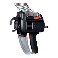
Functional description
8
See the Operating Instructions for the tool for a description
of the power pack.
Description of the connections: à„Pinout of serial interface,
power pack with control box“ on page24.
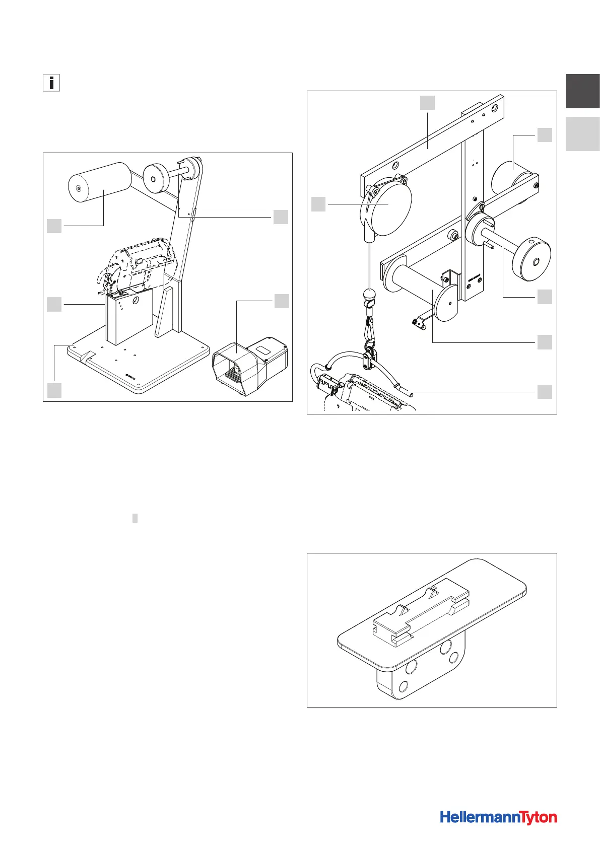
3.3 Bench mount kit CPK
3
2
1
5
4
1 BMK reel mount CPK
2 Foot-operated switch
3 BMK base plate CPK
4 BMK tool mount CPK
5 BMK relay roller
The bench mount kit CPK holds the tool in an upright
position, so the user can guide the bundle past the tool and
use the foot-operated switch to trigger tying, à„Installing
the bench mount kit CPK“ on page11.
Foot-operated switch
2 can be used together with the bench
mount kit CPK for easier tying at the tool. It connects to the
power pack with control box.
3.4 Overhead suspension CPK
6
1
2
3
4
5
1 OHS counterweight
2 OHS reel mount CPK
3 OHS relay roller
4 Suspension hanger CPK
5 Balancer
6 OHS rail runner
The overhead suspension CPK is for suspending the tool
from overhead, à„Installing the overhead suspension CPK“
on page14.
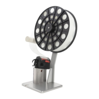
3.5 Robot adapter CPK
The robot adapter CPK is for securing the tool to automated
systems such as robots, à„Installing the robot adapter
CPK“ on page16.