1.2. Basic structure
The basic structure is shown in Figure 1.
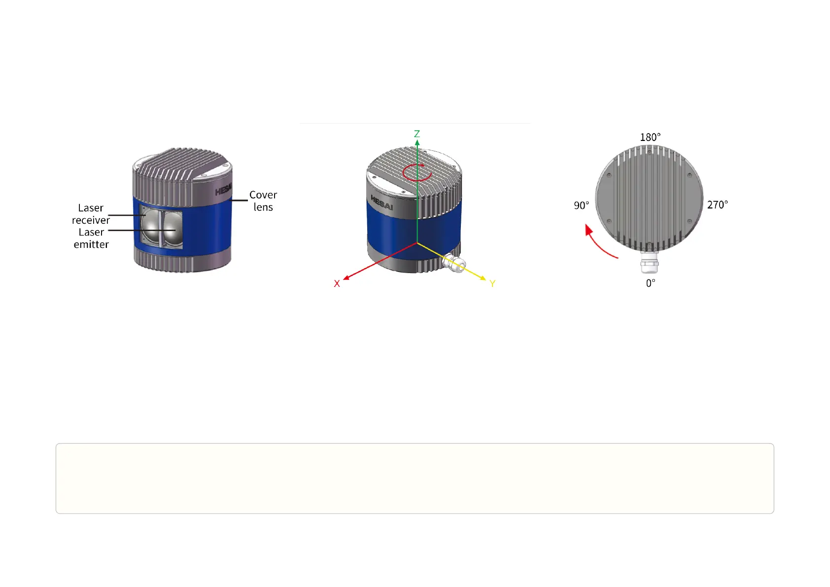
64 pairs of laser emitters and receivers are attached to a motor that rotates 360° horizontally.
Figure 1. Partial cross-sectional diagram Figure 2. Coordinate system (isometric view) Figure 3. Rotation direction (top view)
The lidar's coordinate system is illustrated in Figure 2.
•
Z-axis is the axis of rotation.
•
The origin is shown as a red dot in Figure 5. All measurements are relative to the origin.
The lidar azimuthal position is defined in Figure 3.
•
Y-axis corresponds to 0°.
•
Each laser channel has an intrinsic azimuth offset. Channel 18 is selected to define the lidar's azimuthal position.
For example, when Channel 18 passes the 90° position:
•
the lidar is at the 90° position;
•
the azimuth of the corresponding data block in the Point Cloud Data Packet is 90°.
Pandar64
-11-

 Loading...