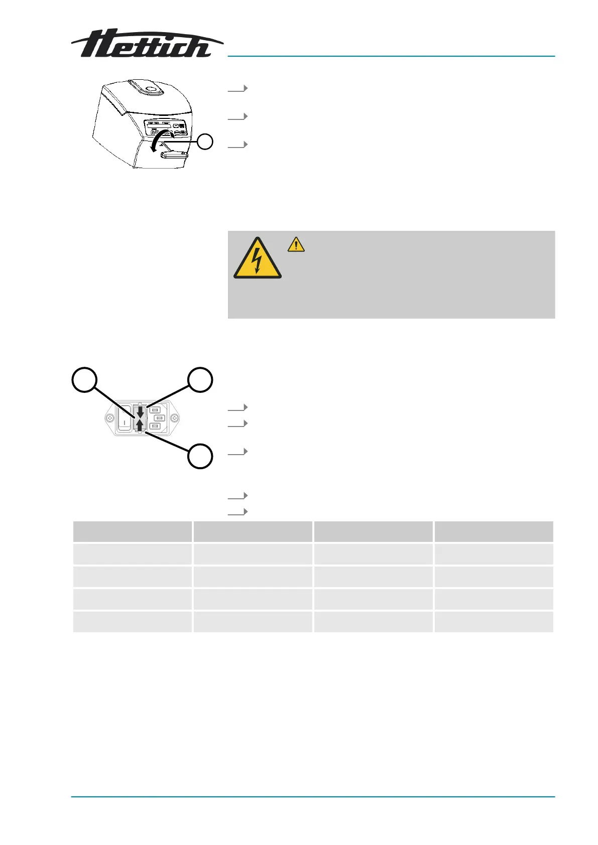
Fig. 16: Emergency release
1 Hole
Fig. 17: Mains input fuse
1 Fuse holder
2 Snap lock
1. Look through the window in the lid to ensure that the rotor is sta-
tionary.
2. Insert the hex key horizontally into the hole (
1
) and turn anticlockwise
until the lid opens.
3. Remove the hex key from the hole (
1
).
9.4
Replacing the mains input fuse
WARNING
Risk of electric shock due to maintenance and servicing
work on live device.
− Disconnect the device from the mains before carrying
out repairs and maintenance.
Personnel:
■ Trained user
The mains fuses are located next to the mains switch.
The mains switch is in switch position
[O]
1.
Disconnect the mains cable from the device plug.
2.
Press the snap locks (
2
) against the fuse holder (
1
) and pull them
out.
3.
Replace the defective mains input fuses.
Only use fuses with the nominal value specied for the type: see the
table below.
4.
Push in the fuse holder (
1
) until the snap lock engages.
5.
Reconnect the device to the mains.
Model Type Fuse Order no.
EBA 200 1800 T 1.6 AH/250 V E891
EBA 200 1800-01 T 3.15 AH/250 V E997
EBA 200 S 1802 T 3.15 AH/250 V E997
EBA 200 S 1802-01 T 6.3 AH/250 V 2266