iCLASS SE Reader Module Hardware Developer’s Guide, SE3200-902, Rev. C.1
February 2014 Page 2 of 52
Contents
1 Introduction ........................................................................................................................... 7
1.1 Product Description ...................................................................................................................................... 7
1.1.1 Key Features ................................................................................................................................................................. 7
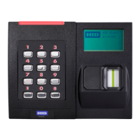
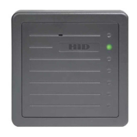
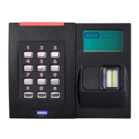
1.1.2 iCLASS SE Reader Module Products ................................................................................................................. 8
1.1.3 Product Guide .............................................................................................................................................................. 9
1.2 Scope/Purpose ............................................................................................................................................... 9
1.3 Terms and Abbreviations .......................................................................................................................... 10
2 Overview ................................................................................................................................ 11
2.1 Features ............................................................................................................................................................. 11
2.2 Block Diagram ................................................................................................................................................ 12
2.3 Theory of Operation .................................................................................................................................... 13
2.3.1 Power Modes .............................................................................................................................................................. 13
2.3.2 Module – Transponder Interaction .................................................................................................................... 13
2.4 Peripheral Circuits ........................................................................................................................................ 14
2.4.1 External Pull-up Resistors ..................................................................................................................................... 14
2.4.2 External Noise Filter ................................................................................................................................................ 14
2.4.3 Adding External LEDs and Beeper ................................................................................................................... 14
2.5 Transitioning from the OEM50, OEM75 and eProxL Modules ................................................... 14
2.5.1 OEM50 .......................................................................................................................................................................... 14
2.5.2 OEM75 ........................................................................................................................................................................... 15
2.5.3 eProx Lock Module .................................................................................................................................................. 15
3 Connector Configuration .................................................................................................. 16
3.1 SE3200Axx Connectors ............................................................................................................................ 16
3.2 SE3210Axx Connectors .............................................................................................................................. 16
3.3 Pin Configuration .......................................................................................................................................... 17
3.3.1 P301 Host Interface Connector........................................................................................................................... 17
3.3.2 P701 Power and I/O Connector.......................................................................................................................... 17
3.3.3 P702 Board to Board Connector ....................................................................................................................... 18
3.3.4 P401 HF Antenna Connector ............................................................................................................................... 19
3.3.5 E501/E502 Prox Antenna Connector .............................................................................................................. 19
4 Mechanical Specifications ................................................................................................ 20
4.1 SE3200Axx .................................................................................................................................................... 20
4.2 SE3210Axx ....................................................................................................................................................... 21
4.3 Connector Types ......................................................................................................................................... 22
4.3.1 SE3210Axx Connector Types ............................................................................................................................. 22
4.3.2 SE3200Axx Interconnect ..................................................................................................................................... 22
5 Electrical Specifications ................................................................................................... 23
5.1 Maximum Ratings ........................................................................................................................................ 23
5.2 Current Draw ................................................................................................................................................. 23
5.3 Power Supply ................................................................................................................................................ 24
5.4 Host Interfaces .............................................................................................................................................. 24
5.5 Wiegand .......................................................................................................................................................... 24
5.6 I/O 25
5.7 Regulated Voltage Outputs .................................................................................................................... 25
5.8 RF Interface (13.56 MHz) .......................................................................................................................... 25
5.9 RF Interface (125 kHz/Prox) ................................................................................................................... 26
5.10 Start Up Voltages ........................................................................................................................................ 26