iCLASS SE Reader Module Hardware Developer’s Guide, SE3200-902, Rev. C.1
February 2014 Page 32 of 52
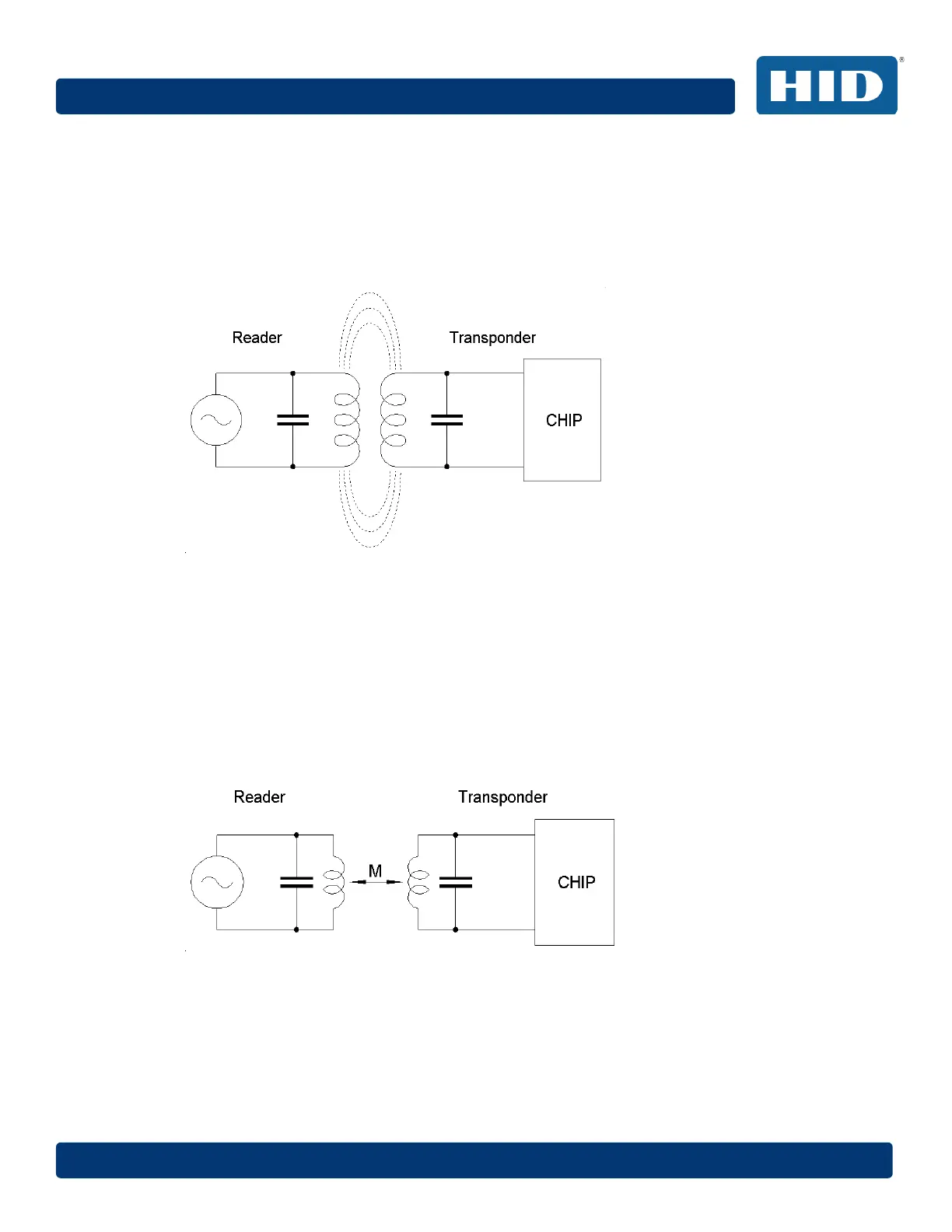
7.1.1 Inductive Coupling
An inductively coupled transponder usually consists of a single chip and an attached
coil, which is used as an antenna.
Most inductively coupled transponders are passive, meaning that power is supplied by
the reader. To this end, the reader produces a magnetic field that the transponder
uses for power.
Figure 12: Inductive Coupling Principle
Mathematically, treat the coupling as a simple alternating magnetic field. The
wavelength at the frequencies of interest is much higher than the distance between
the tag and reader (22.1 m at 13.56 MHz). Both antenna coils (transponder and reader)
have a parallel capacitor, creating a parallel resonant circuit. The capacitor is chosen
to achieve a resonance frequency near the working / carrier frequency of 13.56 MHz.
Interpret the arrangement of the two coils as a loosely coupled transformer, with a
coupling factor that varies with position and geometry.
Figure 13: Mutual Inductance between Reader and Transponder Antenna