CHAPTER 2
Setup and Configuration
14 Studio Command Series User Manual
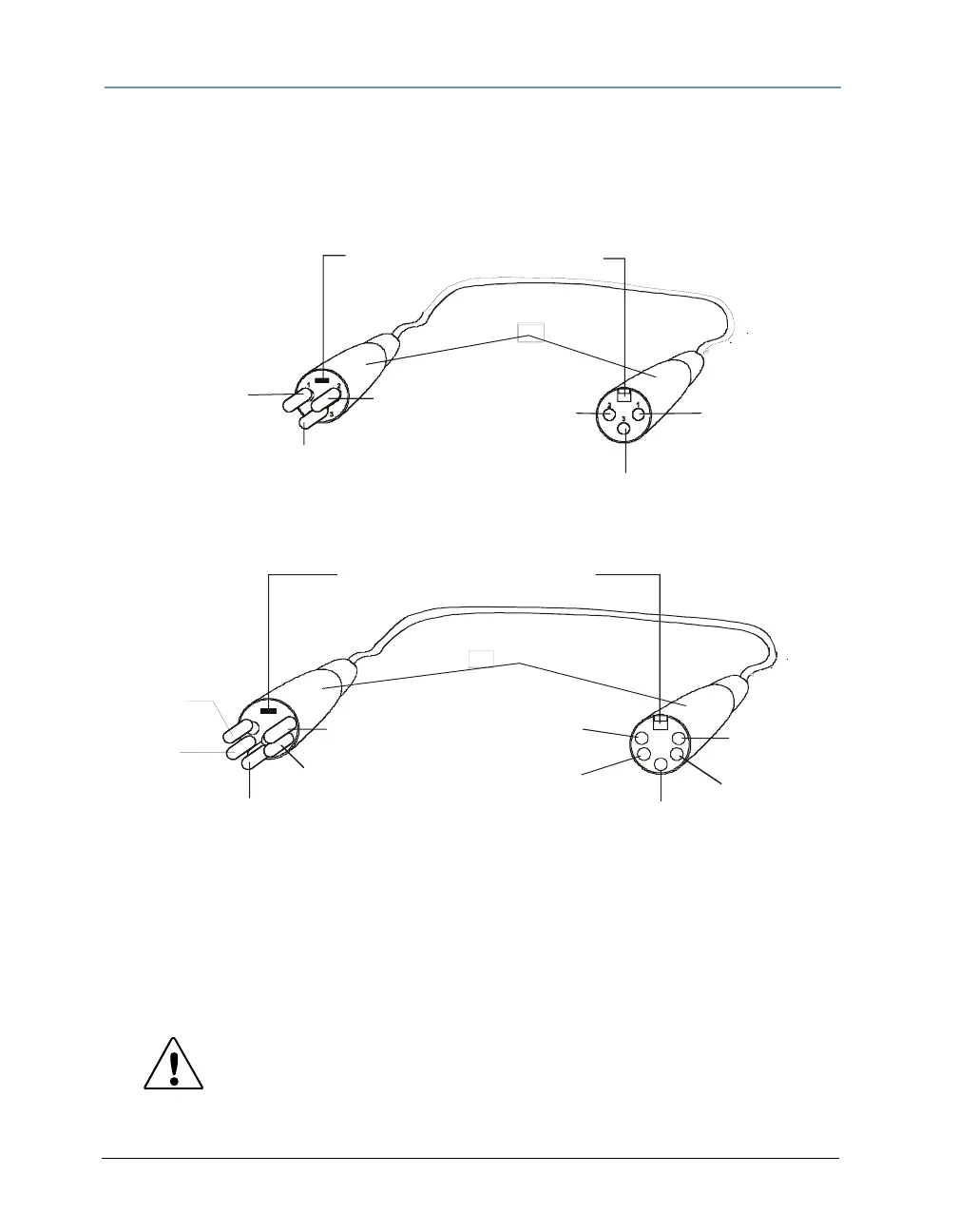
Cable Connectors:
Studio Command 1200/700 fixtures can accept either 3-pin or 5-pin XLR cable connectors.
Studio Command H fixtures use 3-pin XLR cable connectors only. Cabling must have a male XLR
connector on one end of the cable and a female XLR connector on the other end. The following
diagram shows the pin configuration for both cable types.
Test each cable with a voltage/ohm meter (VOM) to verify correct polarity and to make sure that
the negative and positive pins are not grounded or shorted to the shield or to each other.
Caution: Do not connect anything to the ground lug on the XLR
connectors. Do not connect or allow contact between the
common (cable shield) and the fixture’s chassis ground.
Grounding the common could cause a ground loop and/or
erratic behavior.
positive
(data true)
negative
(data
complement)
Common
(cable shield)
positive
(data true)
negative
(data
complement)
XLR shell
Common
(cable shield)
Grounding lug (inside XLR shell)
Male XLR Connector
Female XLR Connector
positive
(data true)*
negative
(data
complement)*
Common
(cable shield)
2
1
3
positive
(data true)
negative
(data
complement)
XLR shell
Common
(cable shield)
1
2
3
4
5
5
4
positive
(data true)*
negative
(data complement)*
negative
(data
complement)
positive
(data true)
*This data line is not used by the fixture, but allows data to pass through the fixture.
Grounding lug (inside XLR shell)
Male 3-pin XLR Connector Female 3-pin XLR Connector
Male 5-pin XLR Connector Female 5-pin XLR Connector
Pin configuration for 3-pin (Studio Command 1200/700 model only) and 5-pin XLR cables