CHAPTER 2
Setup and Configuration
Studio Command Series User Manual 15
Setting Up a DMX Link
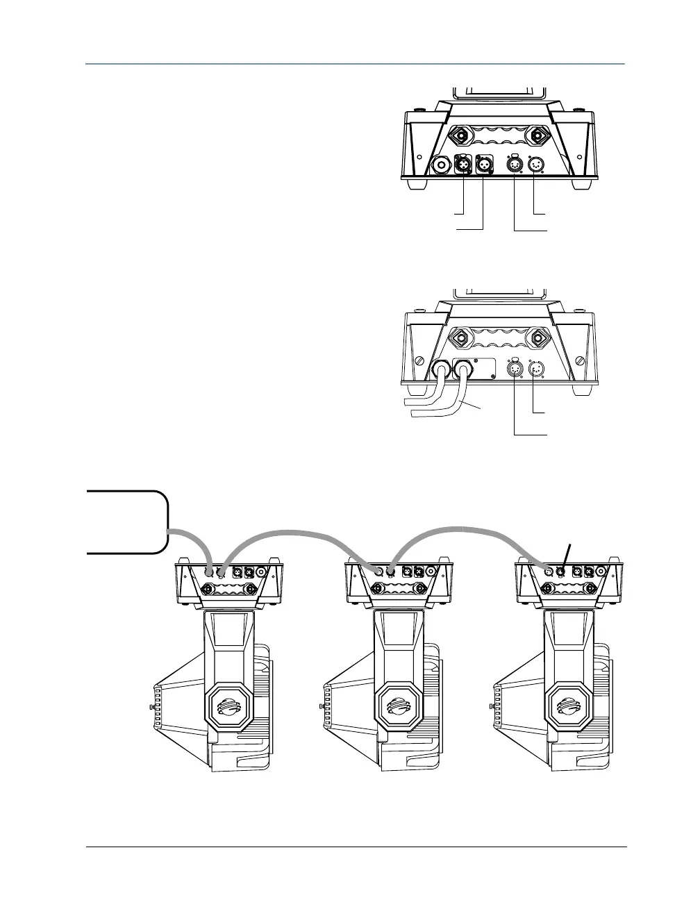
Data cable connectors on
he Studio Command
®
1200/700 fixture pan
3-pin Data Out
5-pin Data In
3-pin Data In
5-pin Data Out
Data cable connectors on
the Studio Command
®
H fixture panel
5-pin Data In
5-pin Data Out
To link one or more fixtures to a controller using
either 3-pin or 5-pin XLR cables:
1. Connect the male XLR connector of a DMX
Data cable to the controller’s DMX Data Out
connector.
2. Connect the Data cable’s female XLR
connector to the Data In connector of the first
(or next) fixture on the DMX link.
3. Continue linking the remaining fixtures
connecting a cable from the Data Out
connector of each fixture to the Data In
connector of the next fixture on the link.
4. Connect a male terminator to the Data Out
connector of the last fixture in the link. For
information on obtaining a terminator, see
Related Products and Accessories on page 4.
DMX
Console
Termination
Resistor
Connecting to a DMX link using 5-pin connectors