CHAPTER 5
General Maintenance
56 Studio Command Series User Manual
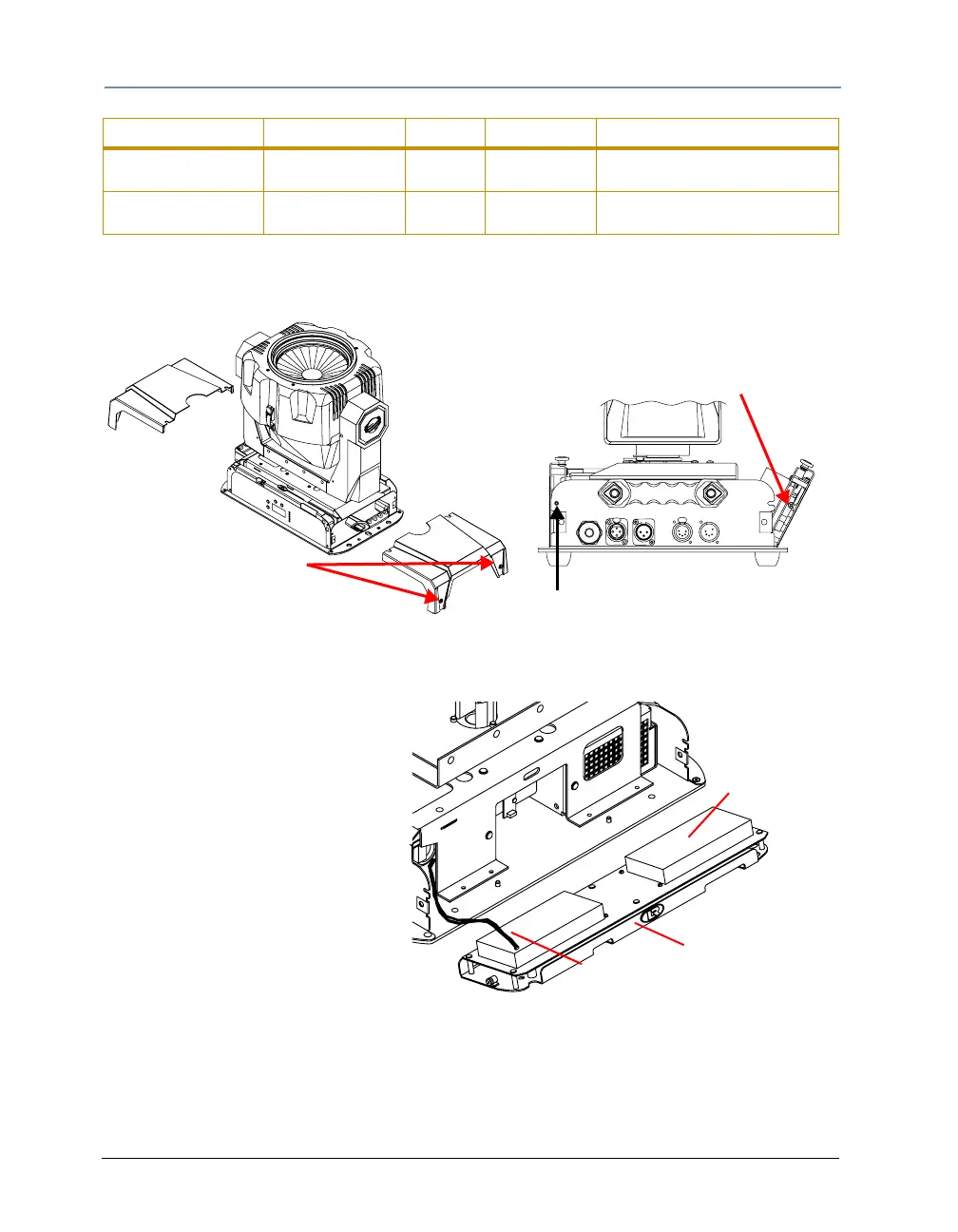
3. Using a wide-tip, flat head screwdriver, loosen the two panel cover retaining screws on each
side of the fixture.
4. Remove the fixture’s two panel covers by sliding them off the fixture.
LED panel retaining screw
(one on each side)
Filter panel retaining screw
(one on each side)
Each panel cover has
two retaining screws
5. To access the logic board fuses or the motor power supply board fuses, use a #2
Phillips-head screwdriver to loosen (but do not remove) the two retaining screws on either
side of the LED display panel.
If you want to access the filter
board fuses, use a #2 Phillips-
h
Logic Board
LED display panel
Motor power supply
board cable
ead screwdriver to loosen (but do
not remove) the two filter panel
retaining screws.
6. Gently lower the desired panel(s).
7. From the LED display panel side of
the fixture, disconnect the motor
power supply cable from the logic
board.
Filter Board F1 16 A, 250 V, Fast
Blow only
5mm x
20mm
Entire fixture Motors will not move, lamp is off,
and fixture appears dead.
Filter Board F2 16 A, 250 V, Fast
Blow only
5mm x
20mm
Entire fixture Motors will not move, lamp is off,
and fixture appears dead.
Fuse Type and Rating Size Protects Symptom of Failure