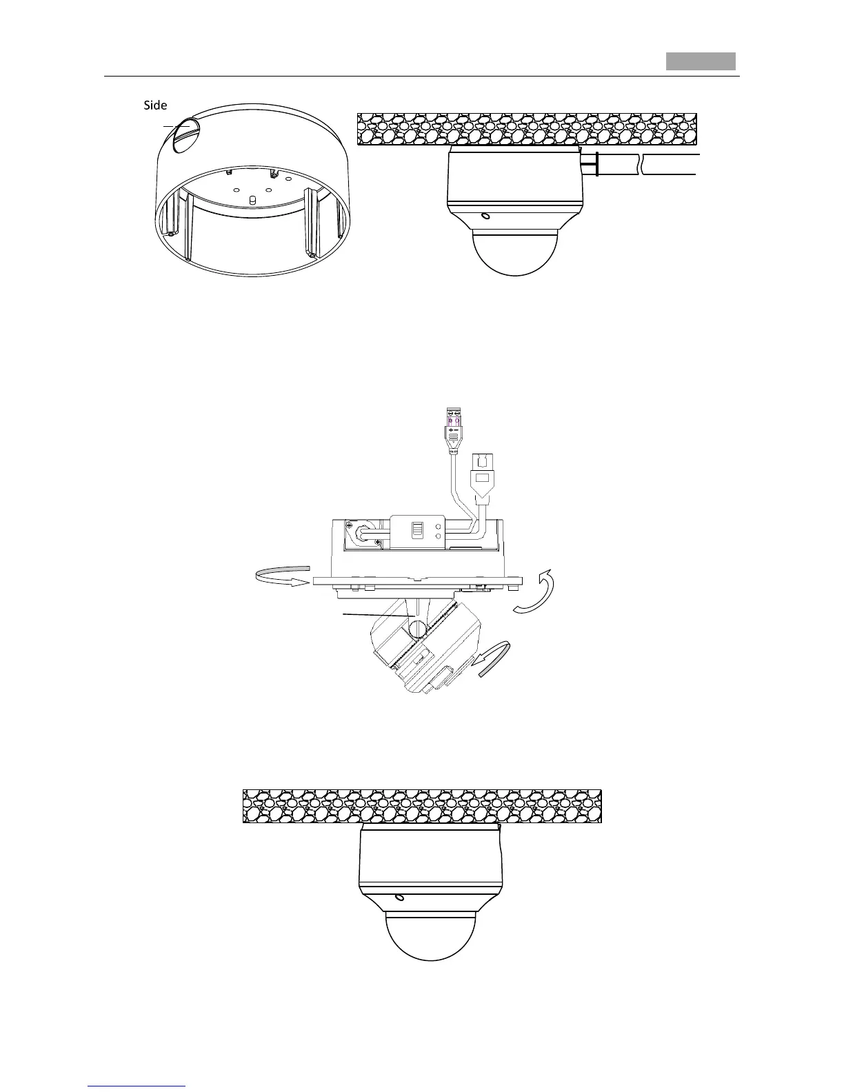
Figure 3-38 Side Cable Routing
5. After connecting the network cable and power cable, view the image of the camera over the
network. Loosen the lock screws; adjust the panning position and tilting position and rotate the lens
to get the desired surveillance angle; fasten the lock screws.
Figure 3-39 Angle Adjusting
6. Reinstall the black liner and bubble to finish the installation.
Figure 3-40 Reinstall
 Loading...