EasyManua.ls Logo

Hioki 3284 User Manual

Hioki 3284
160 pages
To Next Page IconTo Next Page
Page #1 background imageLoading...
Page #1 background image
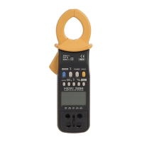
3284
クランプオンAC/DCハイテスタ
CLAMP ON AC/DC HiTESTER
2014年12月 発行 改訂17版
取扱説明書
Instruction Manual
December 2014 Revised edition 17 3284A980-17 14-12H

Questions and Answers:

Hioki 3284 Specifications

General IconGeneral
BrandHioki
Model3284
CategoryMeasuring Instruments
LanguageEnglish

Summary

Introduction

Shipping Check

Check the 3284 Unit and the Supplied Accessories

Verification of main unit, supplied accessories, and optional items.

Safety

Safety Symbols

Explains the meaning of safety symbols used in the manual.

Measurement Categories

Explains measurement categories (CAT II, III, IV) for safe instrument use.

Attentions During Use

Chapter 1 Product Outline

1.1 Product Outline

Overview of the HIOKI 3284 CLAMP ON AC/DC HiTESTER's capabilities.

1.2 Features

Highlights the key features and capabilities of the instrument.

1.3 Parts and Functions

Identifies and explains the function of each part of the instrument.

Chapter 2 Measurement Procedure

2.1 Preparations

Steps required before performing measurements, including battery installation.

2.2 Current Measurement

Core procedures for measuring current with the clamp sensor.

2.2.1 Measuring DC Current (DC A)

Procedure for measuring DC current using the clamp sensor.

2.2.2 Measuring AC Current (AC A)

Procedure for measuring AC current using the clamp sensor.

2.2.3 Measuring AC/DC Current (AC+DC A)

Procedure for measuring AC+DC current using the clamp sensor.

2.2.4 Peak Hold Measurement

How to perform peak hold measurements for current.

2.2.5 Output Function

How to use the output function for recording or waveform monitoring.

2.3 Voltage Measurement

Core procedures for measuring voltage using test leads.

2.3.1 Measuring DC Voltage (DC V)

Procedure for measuring DC voltage using test leads.

2.3.2 Measuring AC Voltage (AC V)

Procedure for measuring AC voltage using test leads.

2.3.3 Measuring AC/DC Voltage (AC+DC V)

Procedure for measuring AC+DC voltage using test leads.

2.3.4 Peak Hold Measurement

How to perform peak hold measurements for voltage.

2.4 Frequency Measurement

Measurement procedures for frequency.

2.4.1 Frequency Measurement in Current Mode

How to measure frequency in current mode.

2.4.2 Frequency Measurement in Voltage Mode

How to measure frequency in voltage mode.

2.4.3 Output Function For Frequency

Details on using the output function for frequency measurements.

2.5 Auto-Zero-Adjustment/Zero-Cancel Correction Function

Essential functions for accurate zeroing and calibration.

2.5.1 Auto-Zero-Adjustment Function

Function for automatically adjusting internal circuit offsets for accurate zeroing.

2.5.2 Zero-Cancel Correction Function

Function to correct zero errors when auto-zero fails.

2.6 Data Hold Function

Freezes the displayed value for easy reading.

2.7 Alteration of Counter Updates

Settings to change display update rates.

2.7.1 SLOW mode

Slows down screen updates for easier reading of fluctuating values.

2.7.2 FAST mode

Speeds up screen updates for measuring rapid changes.

2.8 Recording Function

Records maximum, minimum, and average values during measurement.

Chapter 3 Specifications

3.1 Measurement Specifications

Detailed specifications for measurement accuracy and ranges.

3.1.1 Current Measurement Specifications

Accuracy and range specifications for current measurements.

3.1.2 Voltage Measurement Specifications

Accuracy and range specifications for voltage measurements.

3.2 General Specifications

General specifications including functions, display, and physical attributes.

Chapter 4 Battery Replacement

Chapter 5 AC Adapter (Optional) Use

Chapter 6 Attaching The Hand Strap

Chapter 7 Troubleshooting

Symptom/Remedy Table

Common symptoms and their remedies for troubleshooting the unit.

Chapter 8 Service

Related product manuals