3.8 Using D/A Output
89
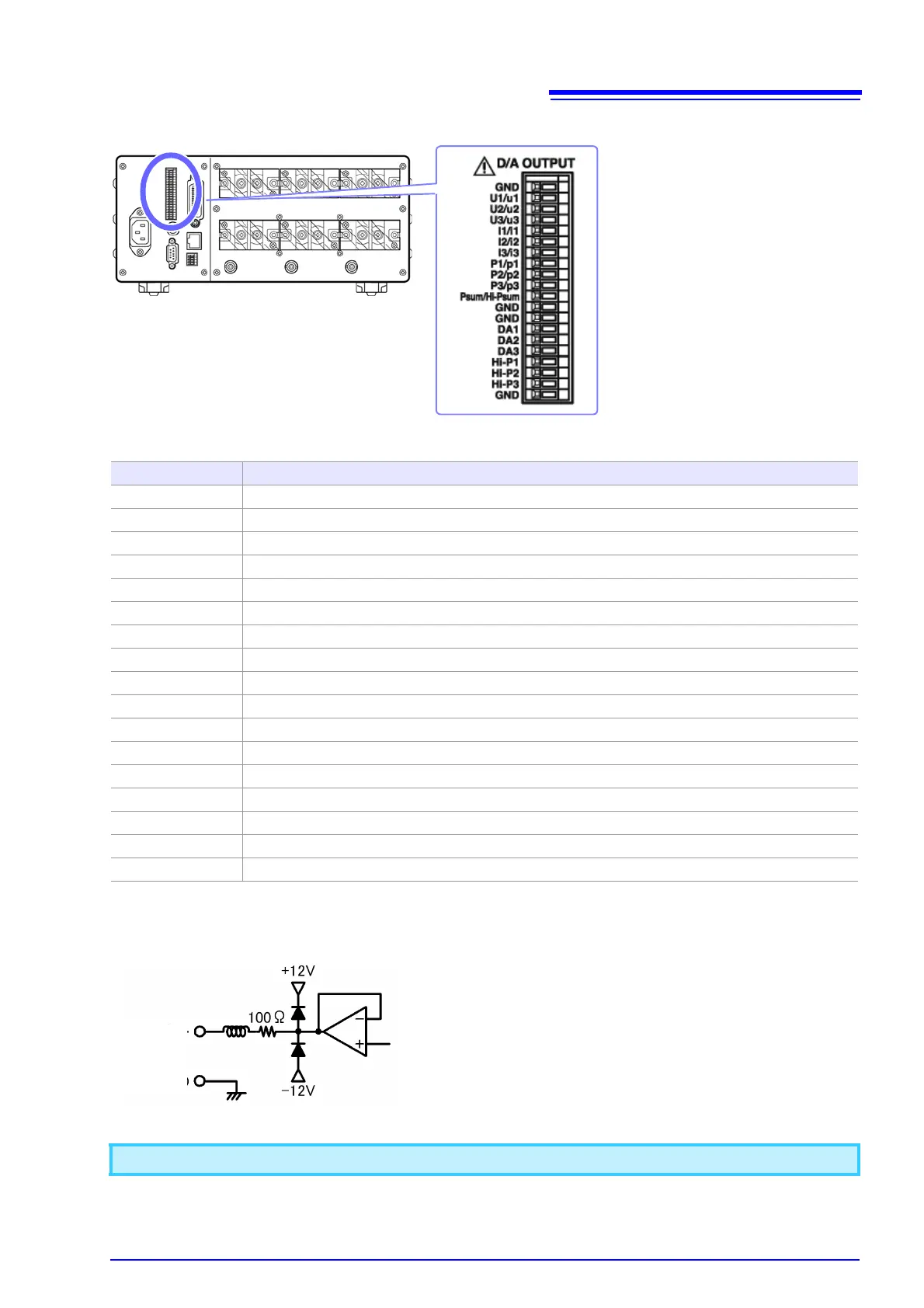
Output terminals and description of output
Output circuits
Terminal name Description
U1/u1 CH1 voltage level output / instantaneous voltage waveform output (selected with settings)
U2/u2 CH2 voltage level output / instantaneous voltage waveform output (selected with settings)
U3/u3 CH3 voltage level output / instantaneous voltage waveform output (selected with settings)
I1/i1 CH1 current level output / instantaneous current waveform output (selected with settings)
I2/i2 CH2 current level output / instantaneous current waveform output (selected with settings)
I3/i3 CH3 current level output / instantaneous current waveform output (selected with settings)
P1/p1 CH1 active power level output / instantaneous power waveform output (selected with settings)
P2/p2 CH2 active power level output / instantaneous power waveform output (selected with settings)
P3/p3 CH3 active power level output / instantaneous power waveform output (selected with settings)
Psum/Hi-Psum Active power sum level output / high-speed active power sum level output (selected with settings)
DA1 Level output for selected parameter
DA2 Level output for selected parameter
DA3 Level output for selected parameter
Hi-P1 CH1 high-speed active power level output (fixed output)
Hi-P2 CH2 high-speed active power level output (fixed output)
Hi-P3 CH3 high-speed active power level output (fixed output)
GND GND
A maximum voltage of approximately ±12 V may be output from D/A output terminals.
Output
terminal
The output impedance of each output terminal is approxi-
mately 100 Ω. When connecting a recorder, DMM, or other
instrument, use a device with high input impedance (1 MΩ or
greater).
 Loading...


