Command Structure 7
© 2001- 2006 Hirschmann Automation and Control GmbH. All Rights Reserved.
Ctrl-E go to end of line
Ctrl-F go forward one character
Ctrl-B go backward one character
Ctrl-D delete current character
Ctrl-H display command history or retrieve a command
Ctrl-U, X delete to beginning of line
Ctrl-K delete to end of line
Ctrl-W delete previous word
Ctrl-T transpose previous character
Ctrl-P go to previous line in history buffer
Ctrl-N go to next line in history buffer
Ctrl-Z return to root command prompt
Tab, <SPACE> command-line completion
Exit go to next lower command prompt
1.1.7 Unit-Slot-Port Naming Convention
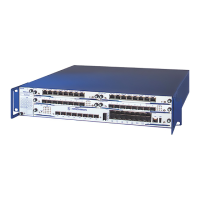
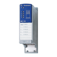
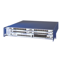
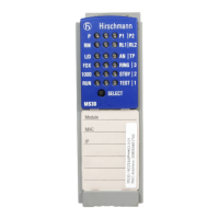
Switch software references physical entities such as cards and ports using a Slot/Port naming
convention. This convention is also used to identify certain logical entities such as Link Aggregation
(LAG) interfaces.
The slot number has two uses. In the case of physical ports it identifies the card containing the ports. In
the case of logical ports it also identifies the type of interface or port.
Physical slot numbers
Physical slot numbers begin with one, and are allocated up to the maximum number of physi-
cal slots
Logical slot numbers
Logical slots immediately follow physical slots and identify LAG or router interfaces. For
LAG the slot number 8 is used. For VLAN interfaces the slot number 9 is used.
The port identifies the specific physical port or logical interface being managed on a given slot.
Physical Ports
The physical ports for each slot are numbered sequentially starting from one.
Logical Interfaces
There are two types of logical interfaces: LAG and VLAN routing interfaces.
LAG interfaces are only used for bridging functions. Each LAG interface consists of a set
of up to eight physical ports identified by their own Slot/Port.
VLAN routing interfaces are only used for routing functions.
 Loading...
