32
Installation SPIDER PL
Release
08
09/2018
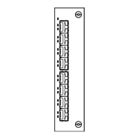
Proceed as follows:
Take the SFP transceiver out of the transport packaging (1).
Remove the protection cap from the SFP transceiver (2).
Push the SFP transceiver with the lock closed into the slot until it latches
in (3).
4.5 Connecting the terminal block
The supply voltage can be connected redundantly. Both inputs are
uncoupled. There is no distributed load. With redundant supply, the power
supply unit with the higher output voltage supplies the device on its own. The
supply voltage is electrically isolated from the housing.
For the supply voltage to be connected, perform the following steps:
Remove the terminal connector from the device.
Connect the wires according to the pin assignment on the device with the
clamps.
Note: With non-redundant supply voltage, the device reports inoperable
supply voltage. You can help prevent this message by applying the supply
voltage via both inputs, or by changing the configuration.
WARNING
ELECTRIC SHOCK
Connect only a supply voltage that corresponds to the type plate of your
device.
Never insert sharp objects (small screwdrivers, wires, etc.) into the
connection terminals for electric conductors, and do not touch the terminals.
Observe the maximum values for the contact load of the signal contact.
Failure to follow this instruction can result in death, serious injury, or
equipment damage.
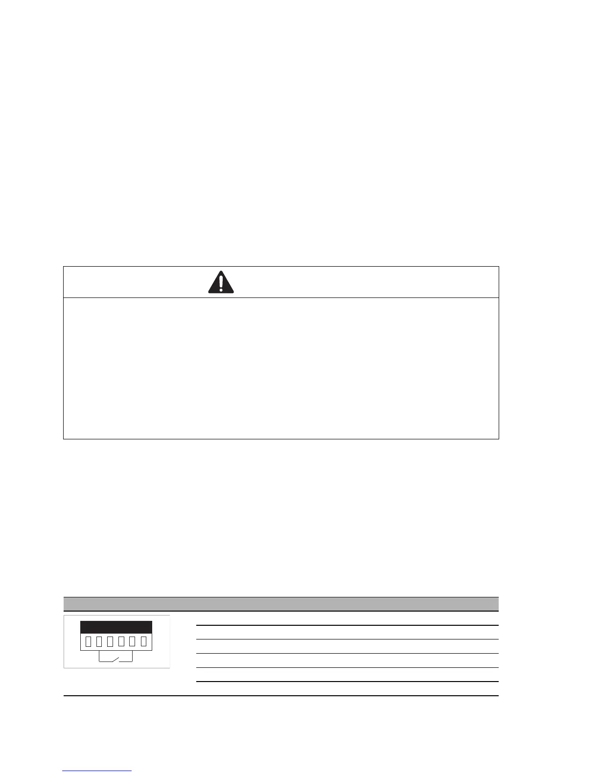
Figure Pin Function
1+ 24 V DC
2FAULT
30 V
40 V
5FAULT
6+ 24 V DC