BASE STATION INTERNAL CONNECTORS
95
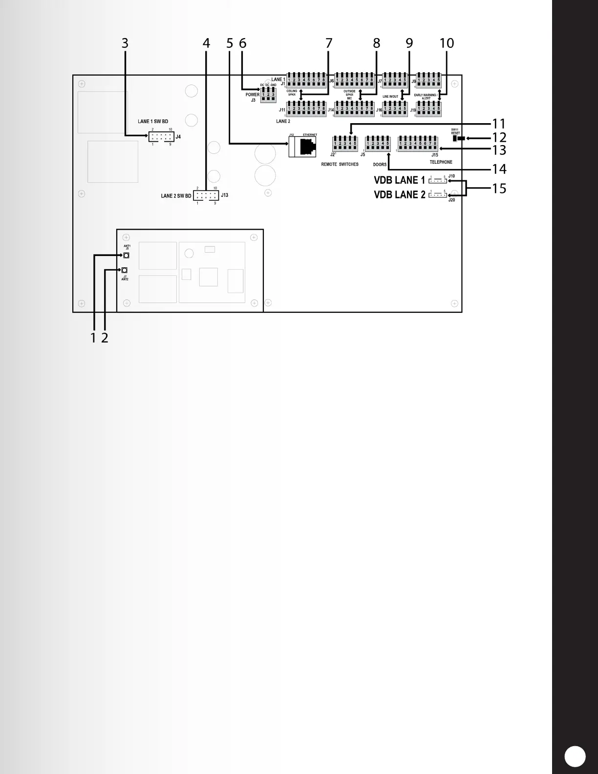
Figure 27. Base station internal connectors and controls
1. ANT1 antenna connector
2. ANT2 antenna connector
3. Switcher board connectors, J4-Lane 1
4. Switcher board connectors, J13-Lane 2
5. Ethernet connector, J12
6. Power connector, J3
7. Ceiling speaker connector, J1-Lane 1, J11-Lane 2
8. Outside speaker/microphone connector, J6-Lane 1, J14-Lane 2
9. Line in/out connector, J7-Lane 1, J16-Lane 2
10. Early warning/alert connector, J9-Lane 1, J19-Lane 2
11. Remote switch connector, J2
12. Reset switch
13. Telephone connector, J15
14. Doors connector for Alert message activation, J5
15. Vehicle detector board (VDB) connector, J10-Lane 1, J20-Lane 2
 Loading...