EQUIPMENT INSTALLATION
20
7. Remove the bracket from the wall and drill two 3/16 inch (4.76mm) holes in the wall at the
marked spots.
8. Insert the enclosed screw anchors into the holes.
9. Place the enclosed screws through the holes in the bracket and screw them into the two screw
anchors to secure the bracket to the wall.
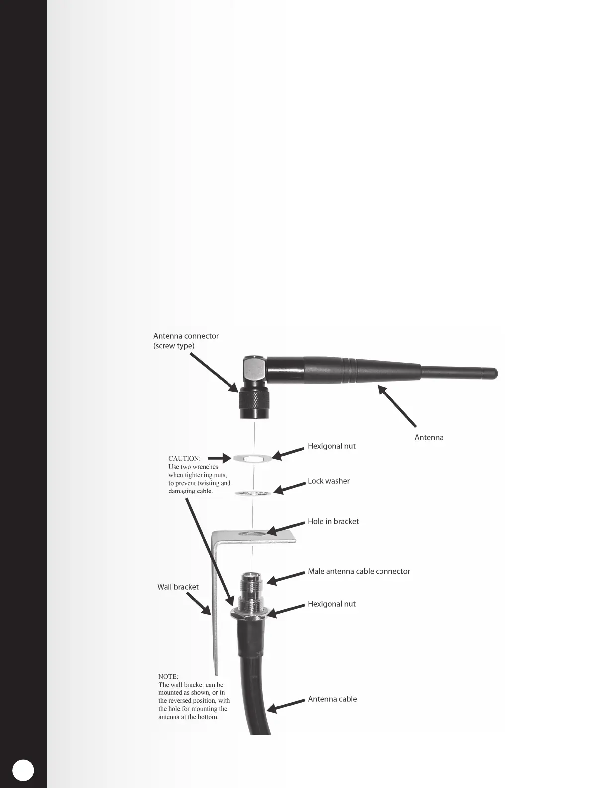
10. Remove the antenna from the antenna cable. DO NOT remove the antenna cable from the
base station.
11. Unscrew the hexagonal nut from the antenna cable connector.
12. Insert the antenna cable connector through the hole in the mounting bracket as shown
in Figure 18, and screw the hexagonal nut onto the connector to secure it in place on the
bracket.
Note: To minimize stress on the bracket, bend the cable to line it up with the bracket before
connecting it.
13. Replace the antenna on the cable connector mounted on the wall.
Note: The best transmission/reception may be achieved with the antenna perpendicular to the
wall. However, if it is a safety hazard or is likely to be bumped and damaged in that position,
it may be necessary for the antenna to be parallel to the wall.
14. Return electrical power to the base station and resume normal operation.
Figure 18. Remote antenna mounting on wall bracket
 Loading...