EQUIPMENT INSTALLATION
22
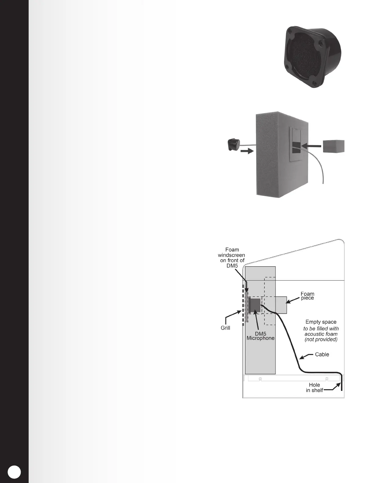
4.4.1 Install DM5 Microphone
Typical DM5 Microphone installation involves placement of the microphone in
a molded foam enclosure and mounting it inside the upper compartment of the
speaker post. You will connect it to the microphone/speaker cable wires from the
drive-thru headset system and ll the empty space behind the unit with acoustic
foam (not provided). If the DM5 is mounted in a small area, its molded foam
enclosure may need to be compressed in order to close the compartment. Follow
these instructions to install the DM5 in a typical speaker post. Installation in
the microphone compartment of a menu board is similar to installation
in a speaker post.
1. Open the speaker post and remove any existing
equipment, foam or debris. If there is an existing
microphone, remove it and disconnect the
microphone cable.
2. Remove the small portion of the provided foam
microphone enclosure, resulting in the two pieces
of foam shown in Figure 20.
3. Insert the DM5 Microphone cable through the hole
in the foam enclosure, and place the microphone
into the hole as shown in Figure 20.
4. Insert the removed piece of foam back into the hole in
the foam enclosure to t snugly against the back of the
microphone, as shown in Figure 20.
5. Using a serrated knife, trim the foam enclosure
so it is ¼ to ½ inch larger than the upper speaker
post compartment (vertically and horizontally) for
a compressed t. Keep the foam pieces to ll the
compartment (if needed).
6. Place the foam windscreen in front of the
microphone, positioning it to cover the inside of
the speaker grill as shown in Figure 21.
7. Place the foam enclosed microphone into the
compartment, so the front of the microphone
windscreen is ush against the metal, centered
on the grill, as shown in Figure 21.
8. Splice the headset system’s microphone cable
wires (new or existing) to the wires of the cable
extending from the back of the DM5, according to
the headset system wiring diagram. Solder the
connection, and then cover the splice with shrink
tubing or crimp caps.
9. Pack acoustic foam (not provided) in the empty
space behind the DM5 Microphone and its foam
enclosure, lling the space.
Figure 19. DM5 Microphone
Figure 20. Placement of DM5
Microphone and foam in the foam
enclosure
Figure 21. Microphone unit in
typical speaker post installation
 Loading...