EQUIPMENT INSTALLATION
24
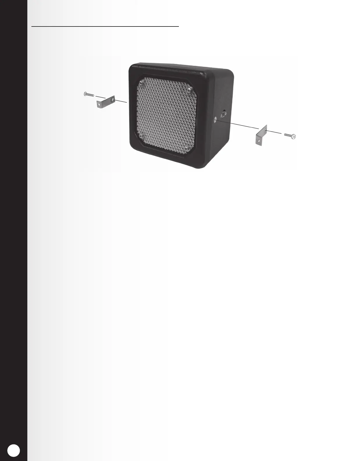
If using the optional mounting brackets:
1. Attach the brackets to the screw inserts on the sides of the speaker unit with the two Phillips
(crosspoint) screws provided as shown in Figure 24.
2. Hold the front of the speaker centered against the speaker grill of the menu board or speaker
post. Mark the menu board or speaker post through the open holes in each of the two
mounting brackets on the speaker, and set the speaker aside.
3. Drill holes at the two marked spots, approximately the same size as the holes in the speaker
mounting brackets.
4. Remove the double-stick tape liner, and press the adhesive side of the gasket against the front
of the speaker in the position shown in Figure 24.
5. Hold the speaker inside the speaker post or menu board with the gasket against the speaker
grill and the holes in the mounting brackets over the two drilled holes.
6. From outside the speaker post or menu board, place the two washers on the enclosed security
screws, and insert the screws through the two drilled holes.
7. Inside the speaker post or menu board, place the locking nuts on the security screws. Tighten
the nuts on the screws only enough to provide a good seal between the gasket and the
enclosure.
8. Place foam around the sides and back of the speaker as shown in Figure 23.
Figure 24. Microphone unit in typical speaker post installation
 Loading...