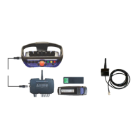
Scanreco G2 radio remote control system
HMF Technical Service Department
Description of Scanreco G2 parameters in the CGW 5355
In the table below is indicated the PWM Mixer parameters in the CGW 5355, the corresponding
menu items and description of functions and parameters.
Please also see examples of setting up operation of crane, stabilizer and extra functions from the
remote control box in this manual.
PWM Mixer ...25.1
Digital
PWM
Digital
Digital ...1.1
K4.1 ENGINE FULL
K4.2 ENGINE START
K4.3 ENGINE STOP
K4.4 ENGINE RPM P
...
K6.9 None
K4.1 ENGINE FULL
PWM ...2.1
PWM Max Current 1000mA
PWM Start Kick 10%
PWM Frequency 200Hz
PWM Dither Freq 70Hz
Source
...
Source
Features ...1.25
Display
Regeneration
Stabilizer con
Remote control
Stab safety sys
PWM Mixer
PWM Mixer
Source ...5.2
PWM 1A, K1.1 Slew
PWM 1B, K1.3 Slew
PWM 2A, K1.5 Boom
PWM 2B, K1.7 Boom
PWM 3A, K1.9 Jib
PWM 3B, K1.11 Jib
PWM 1A, K1.1 Slew
Description of functions and parameters
PWM Mixer
The main function which is to be used when the PWM outputs in the Scanreco G2
radio remote control system are to be set up.
Digital
It is possible to set up 14 digital signals from the K4 and K6 sockets. The K4
outputs are used as standard for engine control signals, and the K6 outputs are
used for extra optional functions.
PWM
It is possible to set up 8 dual outputs (direction A and B) from the K1 and K3
sockets.
The outputs can be set up in order to control PWM signals from the remote control
levers (e.g. proportional control of crane functions) or digital signals (extra optional
PWM Max Current
In this menu item is inserted a value for the current intensity (mA) depending on
whether the system voltage is 24 or 12 volt.
The standard value for 24 volt NEM solenoid valves is 650 mA.
The standard value for 12 volt NEM solenoid valves is 1400 mA.
Start Kick
The function adds extra starting current to ensure a stable starting up of activation
of the valve, as there is stick-slip in the seals etc., when the spool has been in
neutral position for a while.
The standard value is 20 % for the NEM control.
PWM Frequency
The PWM (Pulse Width Modulation) carrier frequency (Hz) states the number of
digital pulses that are controlled with.
The standard value is 200 Hz (pulses per second) for the NEM control.
PWM Dither Freq
The PWM Dither frequency (Hz) is a superposed carrier frequency, which ensures
that the solenoid valve and thereby the spool is kept in constant movement to
prevent stick-slip and give a better regulation.
The standard value is 70 Hz for the NEM control.
 Loading...