Scanreco G2 radio remote control system
HMF Technical Service Department
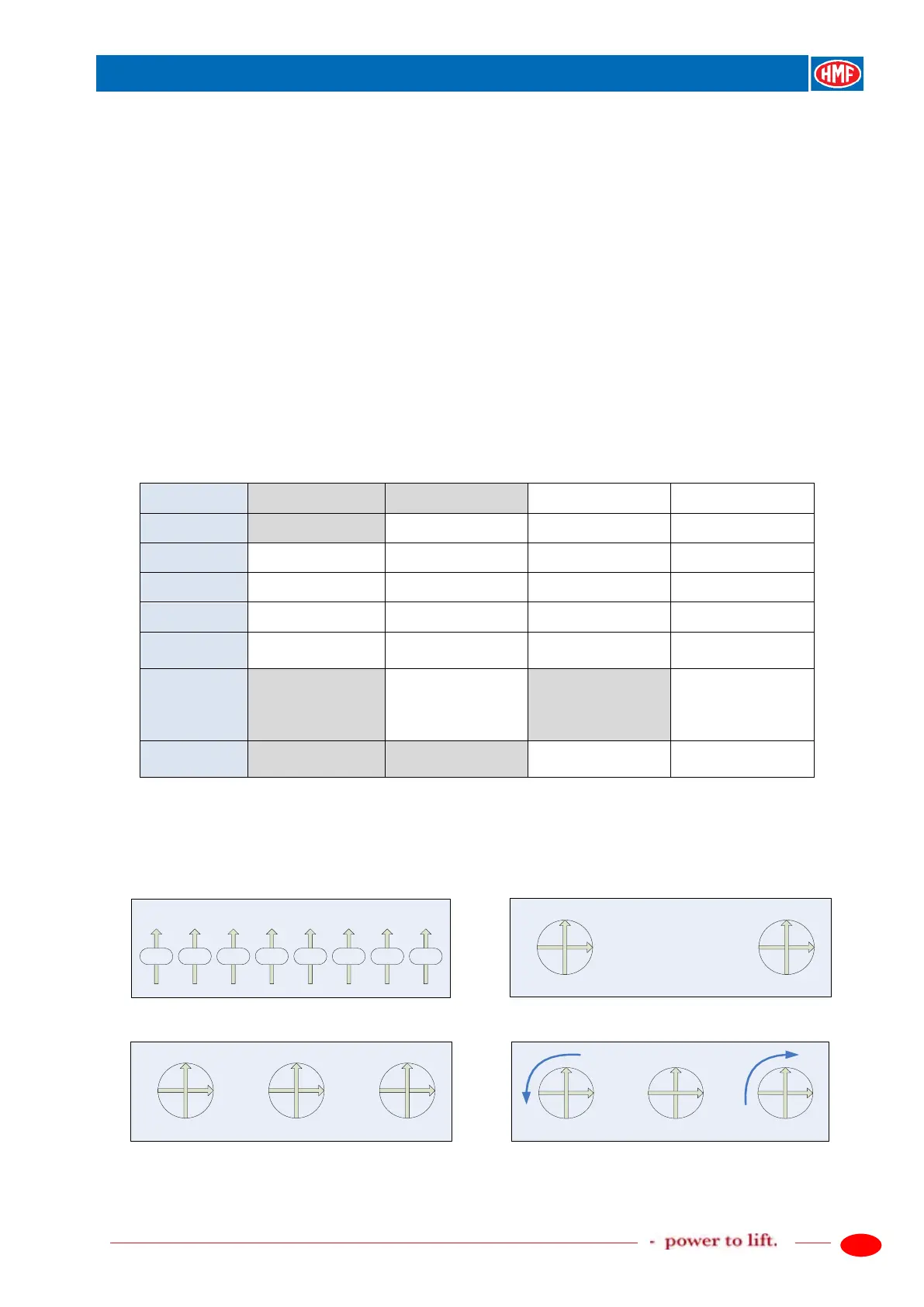
Configuration of remote control levers, operation direction
In the previous chapter, configuration of remote control levers by means of the CGW 5355 is
described. In Lever setup (e.g. Lever setup 1 ENT Lever 1-8, menu 1.1.1.1.2.8.1.1.6-13) the
position of the remote control levers, function, and operation direction are as standard defined as
indicated in the drawing of a remote control box with 8 linear remote control levers:
Remote control boxes with joystick have position, function and operation direction as indicated in
the table and in the drawings: 2-0-2, 2-2-2 and 3-2-3.
Joystick 2 has 2 proportional functions.
Joystick 3 has 3 proportional functions: cross and turn.
Scanreco ”MAXI”, crane functions, operation direction A
Lever 1
Slew right Slew right
Lever 2
Slew right Boom down Boom down
Lever 3
Slew right Boom down Jib up Jib up
Lever 4
Boom down Jib up Extension out Extension out
Lever 5
Jib up Extension out Fly-Jib, jib up Fly-Jib, jib up
Lever 6
Extension out
Fly-Jib, jib up
/ Rotator right
Lever 7
out
/ Grab open up
Rotator right
Lever 8
Winch down
Grab open up
/ Winch down
Scanreco ”MAXI”, position of the levers, operation direction A
 Loading...