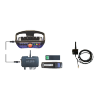
Scanreco G2 radio remote control system
HMF Technical Service Department
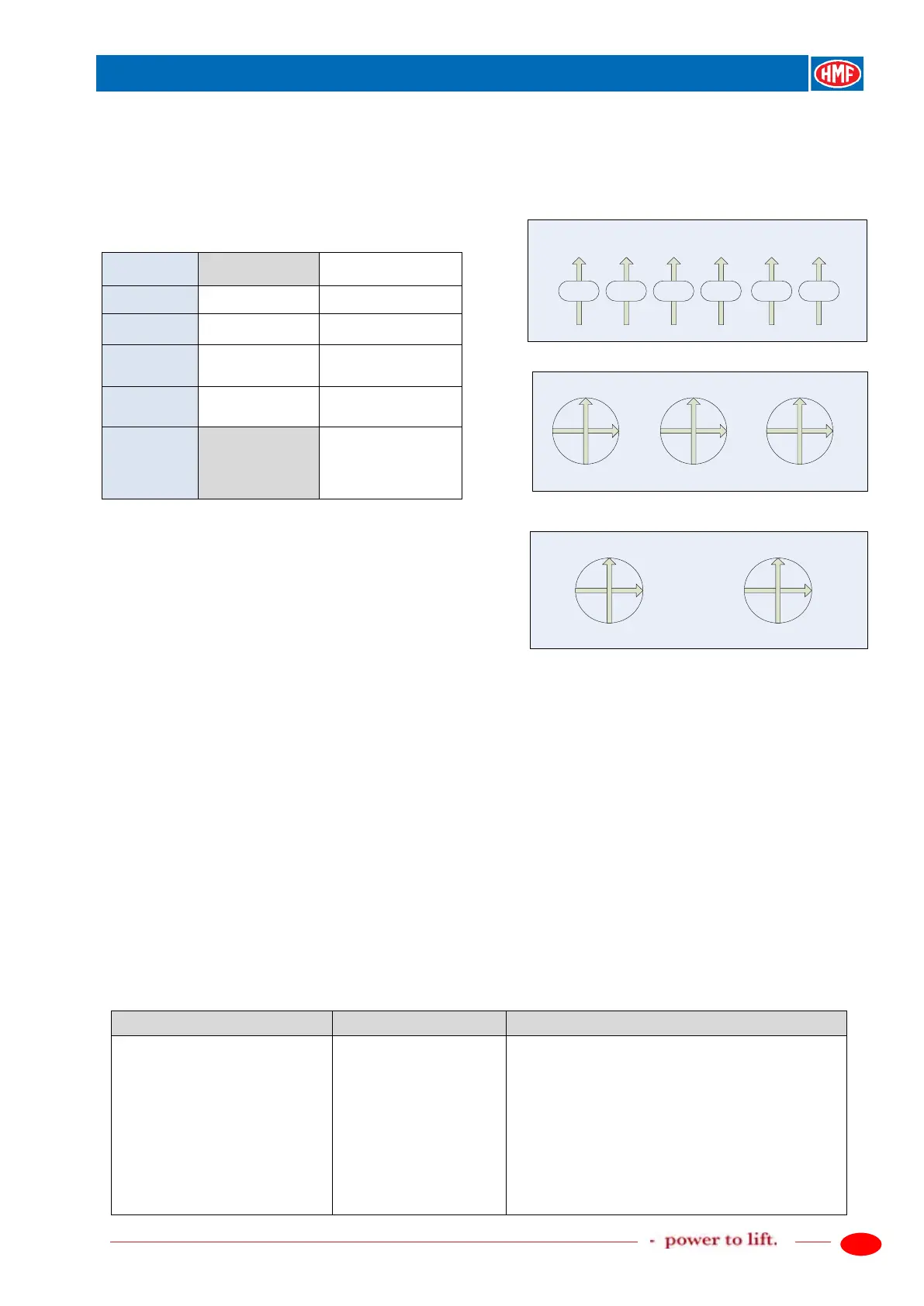
Scanreco "MINI" crane functions,
operation direction A
Scanreco "MINI", position of the levers,
operation direction A
6 linear control levers
4 sections 6 sections
Lever 2 Slew right
Lever 3 Slew right Boom down
Lever 4 Boom down Jib up
Lever 5 Jib up Extension out
Joysticks 2-2-2
Lever 6 Extension out
Fly-Jib, jib up
/ Rotator right
Lever 7
out
/ Grab open up
Joysticks 2-0-2
Set-up, CAN control of the crane functions
In the table below is indicated an example of setting up a radio remote control system consisting
of:
- Danfoss PVG 32 control valve.
- PVED electric activations for crane functions.
- PVEO-DI electric activation on the PVSK section for change between crane mode and stabilizer
mode.
- Scanreco G2 radio remote control.
The RCL 5300 software must be version 29_20 or higher.
The example is a standard set-up valid for cranes where the control valve is fitted on the base of
the crane.
Depending on the equipment there may be used other in- and output terminals in the RCL 5300.
Please also see the chapter "Description of Scanreco G2 parameters in the CGW 5355" and
"Setting up of output signals by means of the CGW 5355" as well as the electric diagram IRC,
G2.
Description of the function
1.1.1.1.3.17 - Remote control
- Activate the feature Remote control.
1.1.1.1.1.17 - Remote control
- Set up the parameters in the Remote control
menu.
- Select Scanreco V2 by means of the arrow key,
ENT.
- Radio controller, serial no. is not indicated.
1.1.1.1.1.17.4 - Recei. SN
- Radio receiver, serial no. is not indicated.
1.1.1.1.1.17.5 - Trans. SN
- Radio transmitter, serial no. is not indicated.
1.1.1.1.1.17.6 - Lever number
- State number of lever functions, ENT.
 Loading...