Scanreco G2 radio remote control system
HMF Technical Service Department
Indications, radio controller
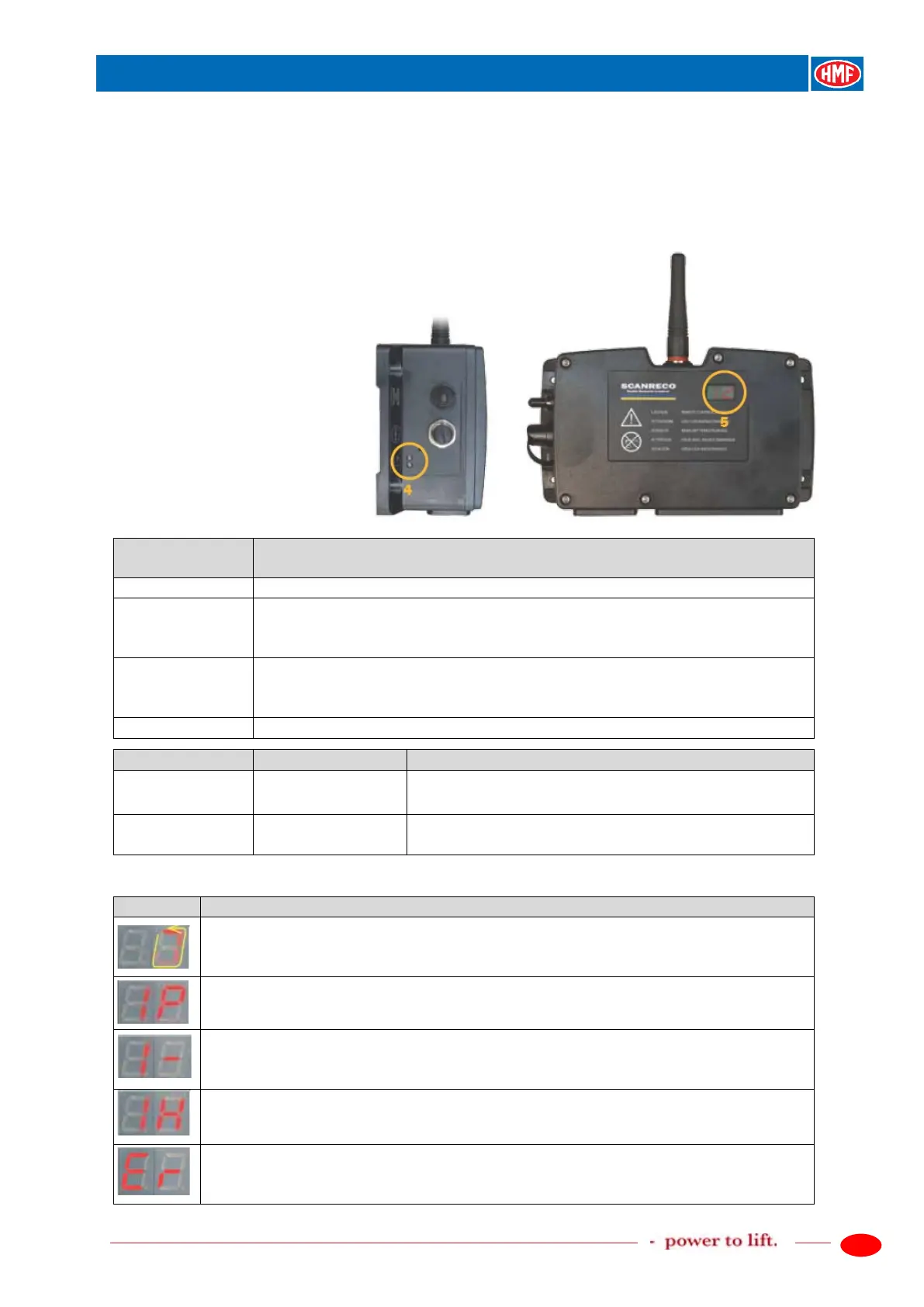
Functional status is indicated two places on the radio controller:
- Two external diodes Status and DV give a general indication (pos. 4).
- The internal LED display gives more detailed information (pos. 5).
The two external diodes
The radio controller is deactivated
The radio controller is activated and the tumbler switch is in Remote
position. There is no connection or communication with the remote
The radio controller is activated and the tumbler switch is in Remote
position. There is connection and communication with the remote control
A system error is indicated (see chapter on error indications).
The dump valve of the control valve is powered
when the tumbler switch is in Manual position.
The dump valve of the control valve is powered after
the first operation of a crane function.
The internal LED display
The radio controller is in stand by mode - no communication with the remote
The radio controller is in stand by mode - there is radio communication with the
remote control box.
There is communication with the remote control box via the remote control
cable.
The ID-code is approved/accepted.
There is radio communication with the remote control box via automatic
continuous frequency hopping (see chapter).
System error - where also the external red diode is flashing.
The internal LED display is flashing, indicating an underlying error code (see