Scanreco G2 radio remote control system
HMF Technical Service Department
Set-up and connection of engine control functions
In the table below is indicated an example of the standard set-up of the engine control functions.
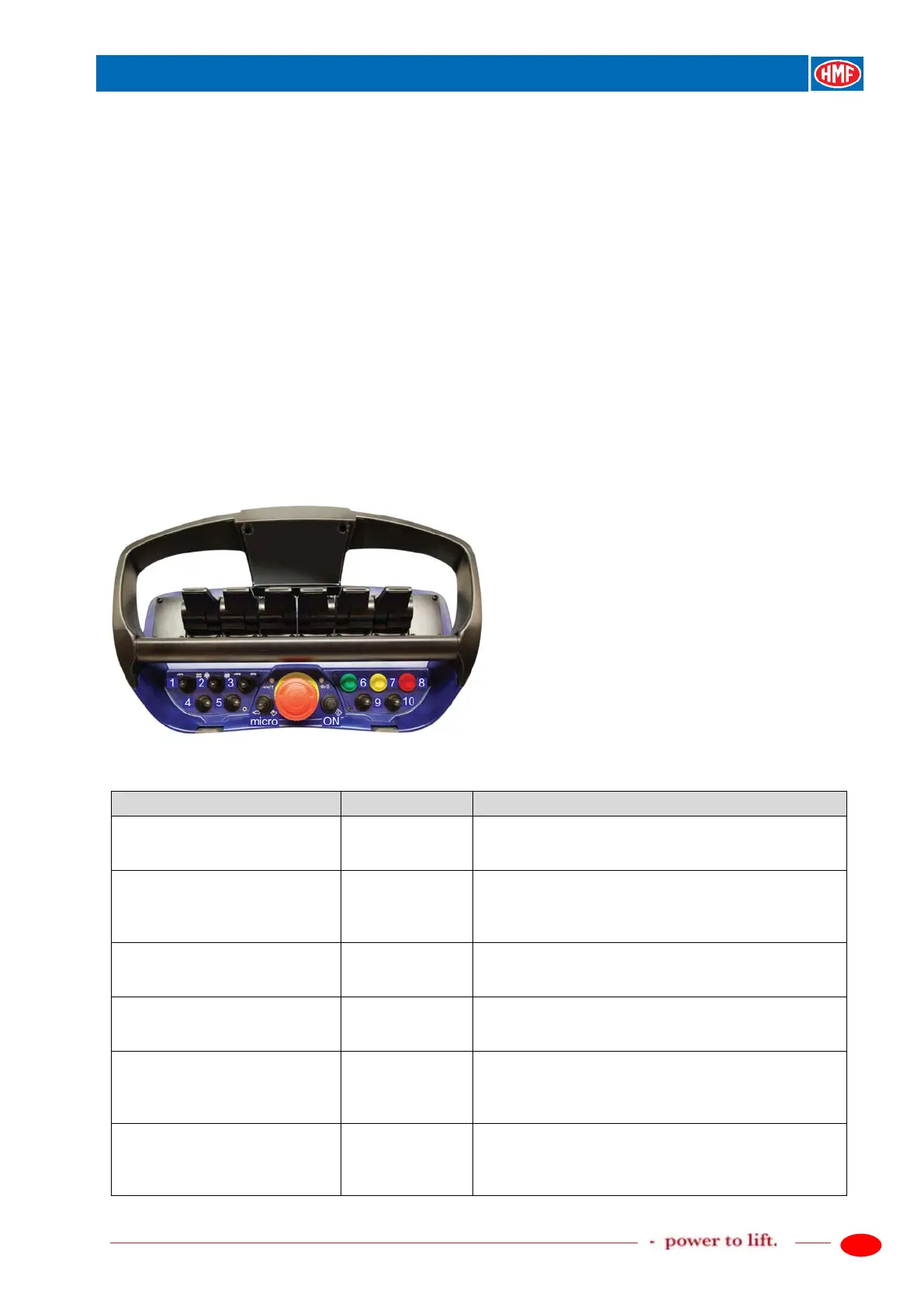
The engine control functions are activated by the tumbler switches 1, 2 and 3 on the remote
control box. When operating an engine function, the configured output terminals in the K4 socket
in the radio controller receive a high signal, which continues onto the conductors of the EX1
cable.
Please also see the detailed description of the engine control functions in the chapter "Setting up
of output signals by means of the CGW 5355" as well as the electric diagrams: IRC, G2 or
NEMRC, G2.
The RCL 5300 software must be version 29_20 or higher.
Description of the function
- Activate the feature PWM Mixer.
- Setting up in PWM Mixer.
- Setting up of digital outputs.
- Signal on the output terminal K4.1 for increasing the
number of revolutions when operating a crane
function:
- Signal on the output terminal K4.2 for starting up
the engine:
- Signal on the output terminal K4.3 for stopping the
engine:
- Signal on the output terminal K4.4 for increasing the
number of revolutions of the engine by each
activation of the tumbler switch no. 3 to the left: select
- Signal on the output terminal K4.5 for reducing the
number of revolutions of the engine by each
activation of the tumbler switch no. 3 to the right: