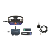
Scanreco G2 radio remote control system
HMF Technical Service Department
Set-up, radio remote control of stabilizer functions
In the table below is indicated an example of setting up radio remote controlled stabilizer
functions in a system consisting of:
- A standard radio remote controlled crane control valve.
- A stabilizer control valve with 8 PWM electric activations - or ON-OFF activations - for operating
the stabilizers of the crane (down/up, extend/retract) as well as a separate traverse (down/up,
extend/retract).
- Scanreco G2 radio remote control.
- CIO 5376 controller
The RCL 5300 software must be version 29_20 or higher.
The example is a standard set-up for cranes configured with the above-mentioned system.
Depending on the equipment there may be used other in- and output terminals in the radio
controller.
Please also see the chapter "Description of Scanreco G2 parameters in the CGW 5355" and
"Setting up of output signals by means of the CGW 5355" as well as the electric diagram:
Stabilizers by remote G2, 4+2 ways.
Description of the function
1.1.1.1.1.15 - Stabilizer con
- Setting up the stabilizer valve with PWM or ON-OFF
electric activations.
1.1.1.1.1.15.3 - Remote n modul
- The box must be ticked off. This offers the
possibility of activating outputs with STB1-16 for
PWM and ON-OFF electric activations.
1.1.1.1.2.3.2.17 - StabSecBut
- Activation of a holding function - the tumbler switch
for "Engine start/stop" is kept to the left -
to be able to
operate the radio remote control of the stabilizers.
1.1.1.1.2.3.2.17.1 - Module
- Activation signal from the radio controller: select -
RemoteControl
1.1.1.1.2.3.2.17.2 - Input
- Activation signal: select Button 22
1.1.1.1.2.3.2.17.3 - Invert
- The signal is not to be inverted - not ticked off.
- The signal must be PNP - not ticked off.
- Activate the feature PWM Mixer.
- Setting up in PWM Mixer.
- Setting up of stabilizer functions.
1.1.1.1.1.25.2.1 - Max Current
- Select the current intensity to 1800 mA at 24 and 12
volt.
1.1.1.1.1.25.2.2 - Start Kick
- Select increased starting current to 20 %.
1.1.1.1.1.25.2.3 - Frequency
- Select the carrier frequency at 200 Hz.
1.1.1.1.1.25.2.4 - Dither Freq
- Select the superposed carrier frequency at 70 Hz.
1.1.1.1.1.25.2.5 - Source
- Setting up the outputs of the radio controller for
operating the functions of the stabilizer control valve.
1.1.1.1.1.25.2.5.1 - 1A, K1.1
- Directional valve for control of oil flow for "stabilizer
legs - up" and "stabilizer beams - retract" on output
1.1.1.1.1.25.2.5.2 - 1B, K1.3
- Directional valve for control of oil flow for "stabilizer
legs - down" and "stabilizer beams - extend" on
output terminal K1.3: STB DIR B
1.1.1.1.1.25.2.5.3 - 2A, K1.5
- Left front stabilizer leg "up/down" on output terminal
K1.5: STB 5
1.1.1.1.1.25.2.5.4 - 2B, K1.7
- Right front stabilizer leg "up/down" on output
terminal K1.7: STB 7
 Loading...