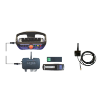
Scanreco G2 radio remote control system
HMF Technical Service Department
Set-up and connection of extra digital outputs
In the table below is indicated an example of the standard set-up of extra digital functions (option)
via the output terminals in the radio controller.
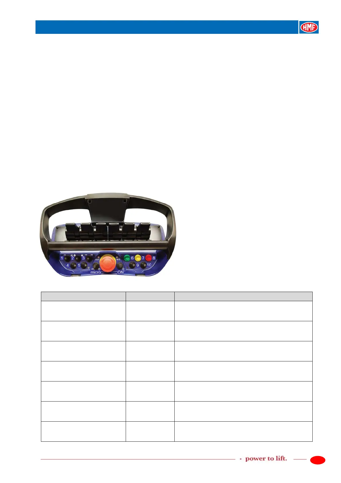
The extra functions are operated by means of the tumbler switches nos. 4, 5 and 9 on the remote
control box. When operating extra digital functions, the configured output terminals in the K6
socket in the radio controller receive a high signal, which continues onto the conductors of the
EX2 cable that are connected to terminals in an extra connection box - Box2.
In case of retro-fitting, you need to order a kit of tumbler switches (4, 5 and 9), an EX2 cable as
well as a Box 2 with terminals.
Please also see the detailed description of the extra digital functions in the chapter "Setting up of
output signals by means of the CGW 5355" as well as the electric diagram: Extra digital outputs,
G2.
The RCL 5300 software must be version 29_20 or higher.
Description of the function
- Activate the feature PWM Mixer.
- Setting up in PWM Mixer.
- Setting up of digital outputs.
- Signal on the output terminal K6.1 for an extra
digital function when activating the tumbler switch no.
4 to the left: select RC But 23 (OPT9).
- Signal on the output terminal K6.2 for an extra
digital function when activating the tumbler switch no.
4 to the right: select RC But 24 (OPT10).
down
- Signal on the output terminal K6.3 for an extra
digital function when activating the tumbler switch no.
5 to the left: select RC But 25 (OPT11).
down
- Signal on the output terminal K6.4 for an extra
digital function when activating the tumbler switch no.
5 to the right: select RC But 26 (OPT12).
down
- Signal on the output terminal K6.6 for an extra
digital function when activating the tumbler switch no.
9 to the left: select RC But 27 (OPT13).
- Signal on the output terminal K6.7 for an extra
digital function when activating the tumbler switch no.
9 to the right: select RC But 28 (OPT14).