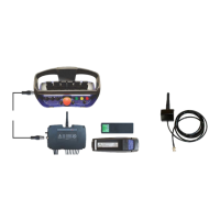
Scanreco G2 radio remote control system
HMF Technical Service Department
- The configuration is activated in stabilizer mode:
select Stb.
1.1.1.1.2.8.1.1.4 - Activation 1
- The configuration lies directly on the remote control
levers. select std.
1.1.1.1.2.8.1.1.5 - Activation 2
- No other operation on the remote control box
necessary to activate the configuration: select OFF.
1.1.1.1.2.8.1.1.6 - Lever 1
- Left front stabilizer beam "extend/retract" is
operated from the 1
st
control lever from the left: select
1.1.1.1.2.8.1.1.7 - Lever 2
- Left rear stabilizer beam "extend/retract" is operated
from the 2
nd
control lever from the left: select Stb.2.
1.1.1.1.2.8.1.1.8 - Lever 3
- Right front stabilizer beam "extend/retract" is
operated from the 3
rd
control lever from the left: select
Stb.3.
1.1.1.1.2.8.1.1.9 - Lever 4
- Right rear stabilizer beam "extend/retract" is
operated from the 4
th
control lever from the left: select
1.1.1.1.2.8.1.1.10 - Lever 5
- Left front stabilizer leg "up/down" is operated from
the 5
th
control lever from the left: select Stb.5.
1.1.1.1.2.8.1.1.11 - Lever 6
- Left rear stabilizer leg "up/down" is operated from
the 6
th
control lever from the left: select Stb.6.
1.1.1.1.2.8.1.1.12 - Lever 7
- Right front stabilizer leg "up/down" is operated from
the 7
th
control lever from the left: select Stb.7.
1.1.1.1.2.8.1.1.13 - Lever 8
- Right rear stabilizer leg "up/down" is operated from
the 8
th
control lever from the left: select Stb.8.
1.1.1.1.2.3.2.18 - Stab right act
The acknowledgement button which is to be pushed
when operating the right stabilizer beam
"extend/retract" is configured in the CIO 5376-1
controller (there may be more CIO controllers in the
1.1.1.1.2.3.2.18.1 - Module
- Configuration of the B processor in the CIO 5376
controller: select CIO5376B 1.
1.1.1.1.2.3.2.18.2 - Input
- Configuration of the input signal when activating the
acknowledgement button: select K369(AD3).
1.1.1.1.2.3.2.18.3 - Invert
- The signal is to be inverted - tick off.
- The signal must be NPN - tick off.
1.1.1.1.2.3.2.19 - Stab left act
The acknowledgement button which is to be pushed
when operating the left stabilizer beam
"extend/retract" is configured in the CIO 5376-1
controller (there may be more CIO controllers in the
1.1.1.1.2.3.2.19.1 - Module
- Configuration of the B processor in the CIO 5376
controller: select CIO5376B 1.
1.1.1.1.2.3.2.19.2 - Input
- Configuration of the input signal when activating the
acknowledgement button: select K370(AD4).
1.1.1.1.2.3.2.19.3 - Invert
- The signal is to be inverted - tick off.
- The signal must be NPN - tick off.