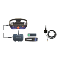
Scanreco G2 radio remote control system
HMF Technical Service Department
Description of the function
- Activate the feature - Display - if the remote control
box has a display fitted.
- Activate the feature PVED.
- Each single PVED electric activation, which is fitted
on the control valve, is programmed for the respective
crane functions.
- Activate the feature Engine.
- Mark the required engine control functions.
- A cross (ticked off) indicates that the function has
been selected.
1.1.1.1.2.2.4 - PVSK-PVEO-DI
- Activate the PVEO electric activation for the PVSK
section of the PVG 32 control valve. A cross (ticked
off) indicates that the function has been selected.
1.1.1.1.2.3.2.6 - Wire sec
- Configure the Wire Security signal from the G2 radio
controller as input signal to the RCL 5300.
1.1.1.1.2.3.2.6.1 - Module
- Input signal to the RCL 5300B processor.
- Configuration of the input terminal K384.
- The signal is not to be inverted (not ticked off).
- The signal must be PNP (not ticked off).
1.1.1.1.2.4.1.1 - O1 K397
- Configuration of the output signal for activation of
the PVEO-DI electric activation on the PVSK-module.
1.1.1.1.2.4.1.1.1 - Min current
- Set the minimum current at 0 mA.
1.1.1.1.2.4.1.1.2 - Max current
- Set the maximum current at 2000 mA.
1.1.1.1.2.4.1.1.3 - Signal
- Output signal for activation of the PVEO-DI electric
activation - crane mode
1.1.1.1.2.4.1.2 - O1 K395
- Configuration of the output signal for activation of
the PVEO-DI electric activation on the PVSK-module.
1.1.1.1.2.4.1.2.1 - Min current
- Set the minimum current at 0 mA.
1.1.1.1.2.4.1.2.2 - Max current
- Set the maximum current at 2000 mA.
1.1.1.1.2.4.1.2.3 - Signal
- Output signal for activation of the PVEO-DI electric
activation - stabilizer mode.
1.1.1.1.2.3.2.25 - PVSK dump
- Configuration of the input signal from the PVEO-DI
electric activation on the PVSK-module.
1.1.1.1.2.3.2.25.1 - Module
- Input signal (feedback) to the RCL 5300B processor
informing that the PVSK-module is moved towards
- Configuration of the input terminal K387.
- The signal is not to be inverted (not ticked off).
- The signal must be PNP (not ticked off).
1.1.1.1.2.3.2.26 - PVSK shift
- Configuration of the input signal from the PVEO-DI
electric activation on the PVSK-module.
1.1.1.1.2.3.2.26.1 - Module
- Input signal to the RCL 5300B processor informing
that the PVSK-module is moved towards stabilizer
- Configuration of the input terminal K388.
- The signal is not to be inverted (not ticked off).
- The signal must be PNP (not ticked off).
1.1.1.1.2.7 - Valve function
- Configuration of the crane functions included in the
current crane control valve.
1.1.1.1.2.7.1 - Primary function
- Select the first of two possible configurations.
1.1.1.1.2.7.1.1 - Valve 1
- Select the first crane function (e.g. Slew), ENT.
1.1.1.1.2.7.1.1 - Valve 2
- Select the second crane function (e.g. Boom), ENT.
- Select all relevant crane functions.
 Loading...