. A complete Parts List is available at www.HobartWelders.com
OM-260 273 Page 20
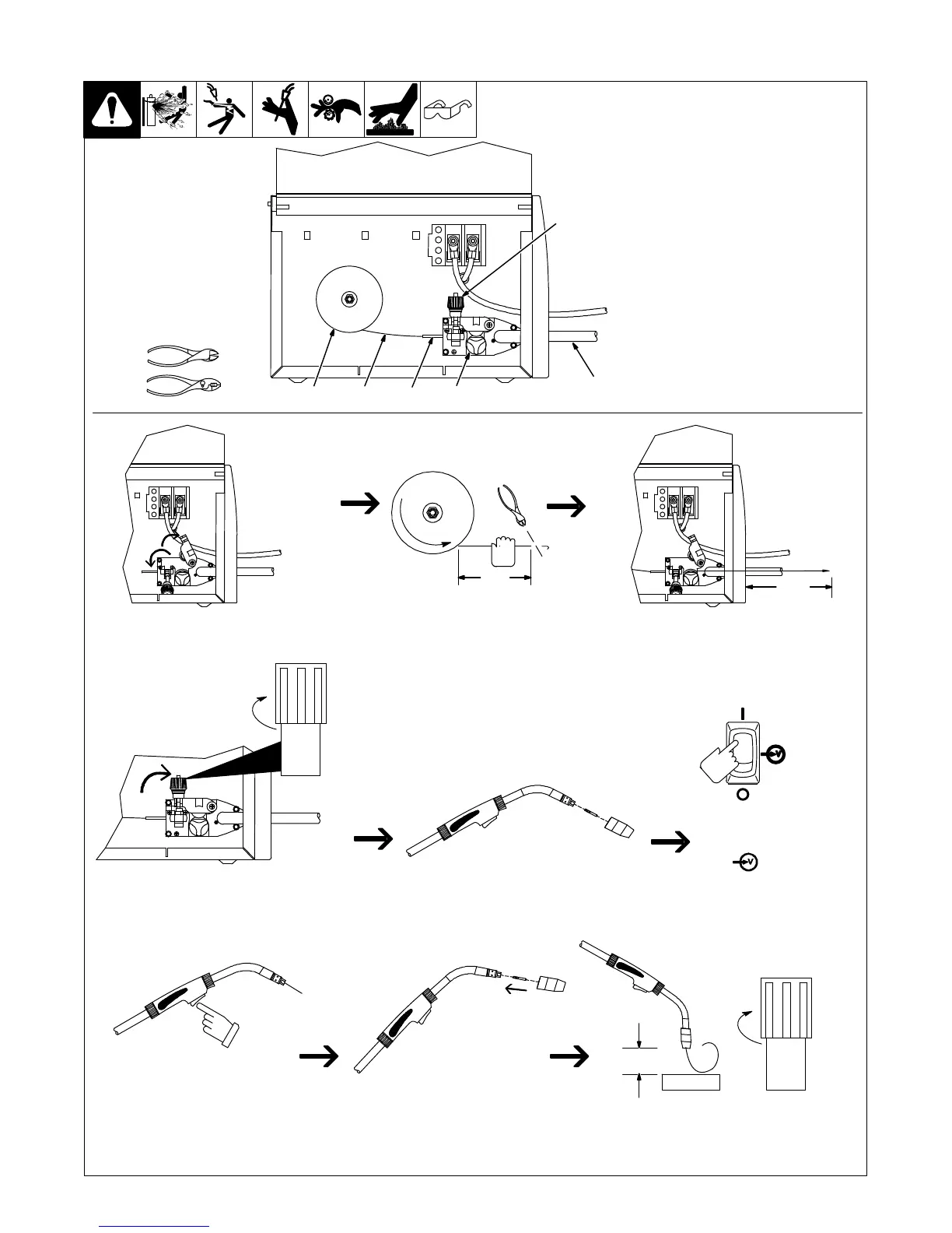
SECTION 6 − OPERATION
6-1. Controls
1 Wire Speed Control
Use control to select a wire feed speed. As
Voltage switch setting increases, wire
speed range also increases (see weld
setting label in welding power source or
Section 6-2, as applicable).
2 Power Switch
3 Voltage Switch
The higher the selected number, the
thicker the material that can be welded
(see weld setting label in welding power
source or Section 6-2, as applicable). Do
not switch under load.
. Switch must “click” into detent
position.
4 Gun Trigger Receptacle
5 Trigger Switch
When pressed, energized wire feeds and
shielding gas flows.
Ref. 248 840-A / Ref. 246 668-A
5
2
3
1
4