OM-260 273 Page 31
9-8. Troubleshooting − Excessive Spatter
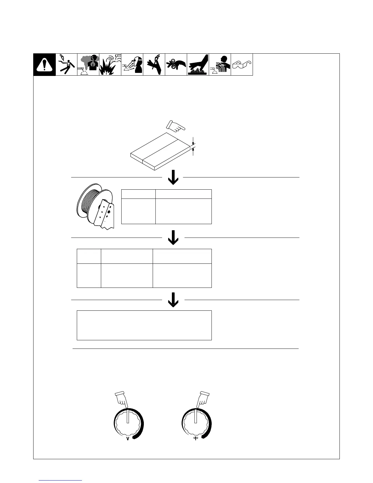
Excessive Spatter − scattering of molten metal particles that
cool to solid form near weld bead.
S-0636
Possible Causes Corrective Actions
Wire feed speed too high. Select lower wire feed speed.
Voltage too high. Select lower voltage range.
Electrode extension (stickout) too long. Use shorter electrode extension (stickout).
Workpiece dirty. Remove all grease, oil, moisture, rust, paint, undercoating, and dirt from work surface before welding.
Insufficient shielding gas at welding arc. Increase flow of shielding gas at regulator/flowmeter and/or prevent drafts near welding arc.
Dirty welding wire. Use clean, dry welding wire.
Eliminate pickup of oil or lubricant on welding wire from feeder or liner.
Incorrect polarity. Check polarity required by welding wire, and change to correct polarity at welding power source.
9-9. Troubleshooting − Porosity
Porosity − small cavities or holes resulting from gas pockets
in weld metal.
S-0635
Possible Causes Corrective Actions
Insufficient shielding gas at welding arc. Increase flow of shielding gas at regulator/flowmeter and/or prevent drafts near welding arc.
Remove spatter from gun nozzle.
Check gas hoses for leaks.
Place nozzle 1/4 to 1/2 in. (6-13 mm) from workpiece.
Hold gun near bead at end of weld until molten metal solidifies.
Wrong gas. Use welding grade shielding gas; change to different gas.
Dirty welding wire. Use clean, dry welding wire.
Eliminate pick up of oil or lubricant on welding wire from feeder or liner.
Workpiece dirty. Remove all grease, oil, moisture, rust, paint, coatings, and dirt from work surface before welding.
Use a more highly deoxidizing welding wire (contact supplier).
Welding wire extends too far out of nozzle. Be sure welding wire extends not more than 1/2 in. (13 mm) beyond nozzle.
9-10. Troubleshooting − Excessive Penetration
Good Penetration
Excessive Penetration − weld metal melting through base metal
and hanging underneath weld.
Excessive Penetration
S-0639
Possible Causes Corrective Actions
Excessive heat input. Select lower voltage range and reduce wire feed speed.
Increase travel speed.